
This circuit produces the sound of the sirens of the American police vehicles. The circuit has good audio power and can be powered by 9 to 12 V voltages.
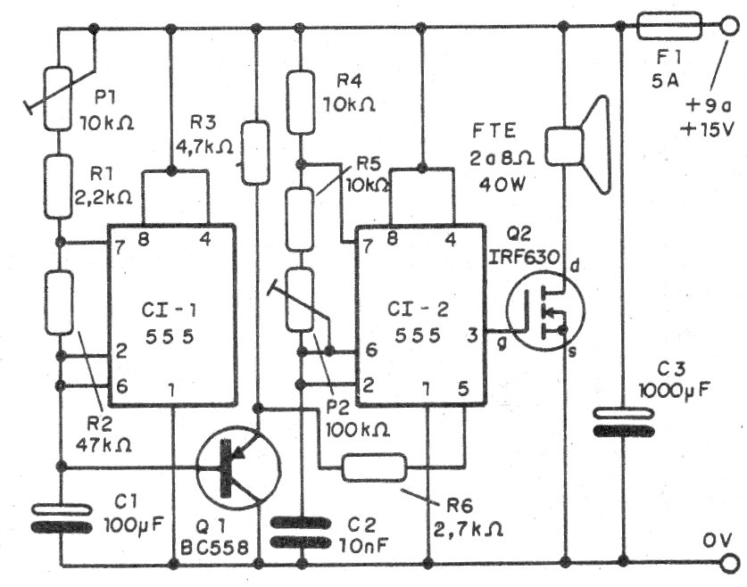
The circuit consists of two oscillators with integrated 555 circuits, one being responsible for modulation and the other for tone.
The modulation signals are controlled by a transistor in order to vary the tone generated by the tone oscillator.
The final signal is amplified by a power MOSFET, but bipolar transistors such as TIP31 can be used provided a 1k resistor is added in series with the base.
In figure 1 we have the complete diagram of the siren.
The assembly may be made on the basis of a printed circuit board with the pattern shown in figure 2.
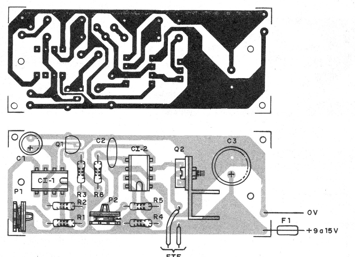
The trimpots must be adjusted to obtain the desired sound, compensating for variations in values of the components due to their tolerance.
The resistors are all 1/8 W and the electrolytic capacitors to 16 V or more.
The power can be made by battery or source, but in case of the source it must have at least 2 A of current.
Material list
CI-1, CI-2 - 555 - integrated circuits
Q1 - BC548 - NPN general purpose transistor
Q2 - IRF640 or any power MOSFET
FTE - 2 to 8 ohms x 10 cm or larger - heavy
P1 - 10 k ohms - trimpot
P2 - 100 k ohms - trimpot
R1 - 2k2 ohms - resistor - red, red, red
R2 - 47 k ohms - resistor - yellow, violet, orange
R3 - 4k7 ohms - resistor - yellow, violet, red
R4, R5 - 10 k ohms - resistors - brown, black, orange
R6 - 2k7 ohms - resistor - red, violet, red
C1 - 100 uF - electrolytic
C2-10 nF- ceramic or polyester
C3 - 1000 uF - electrolytic
Several:
Printed circuit board, heat sink for transistor, mounting box, wires, solder, etc.


