
The simple charger we describe is for AA and AAA batteries, and the type of battery pack used for cordless phones and other devices. The circuit is not insulated from the power grid and must therefore be handled with care.
Wireless phone batteries are made up of sets of batteries that can be harnessed to power your electronic designs.
Each cell supplies 1.2 V with a current that can reach 200 mA and for its charge what we need is a simple charger like the one we described in this article.
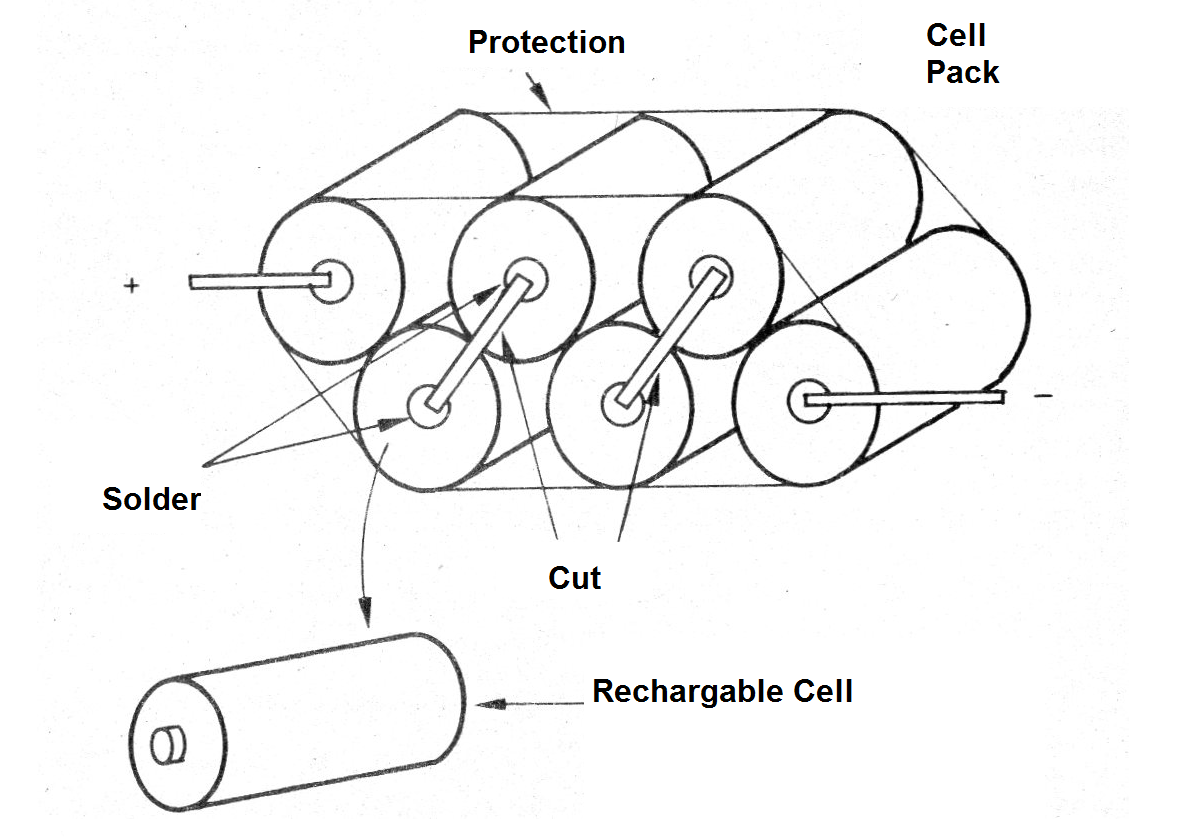
If we have a set of these cells that no longer works, this can occur because only one or two of the cells is in trouble, which means that we can take advantage of the others, as shown in figure 1.
The charger that we describe can work in the network of 110 V and 220 V being very simple to assemble.
We should only be careful to touch any of its parts when in operation, as it is not isolated from the mains, it can cause dangerous shocks.
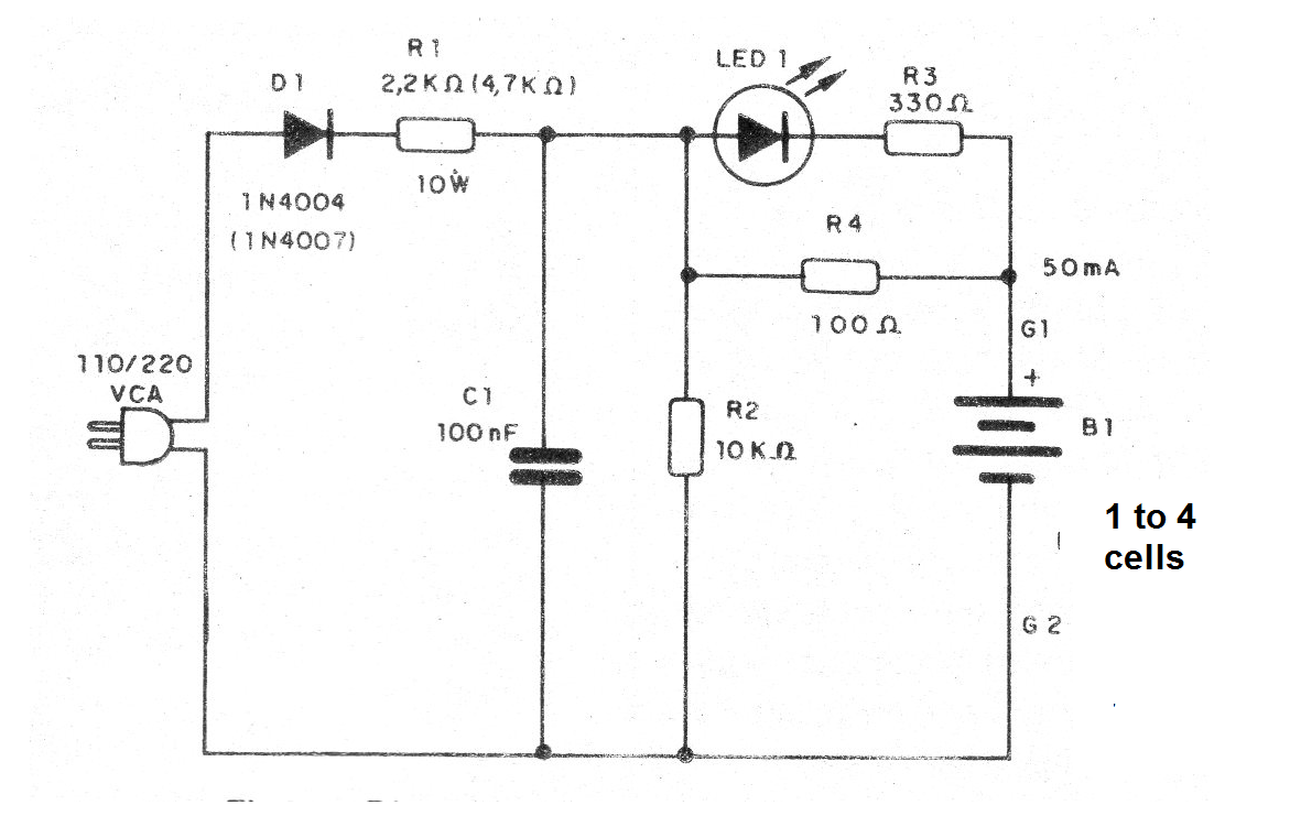
In figure 2 we have the complete diagram of the charger.
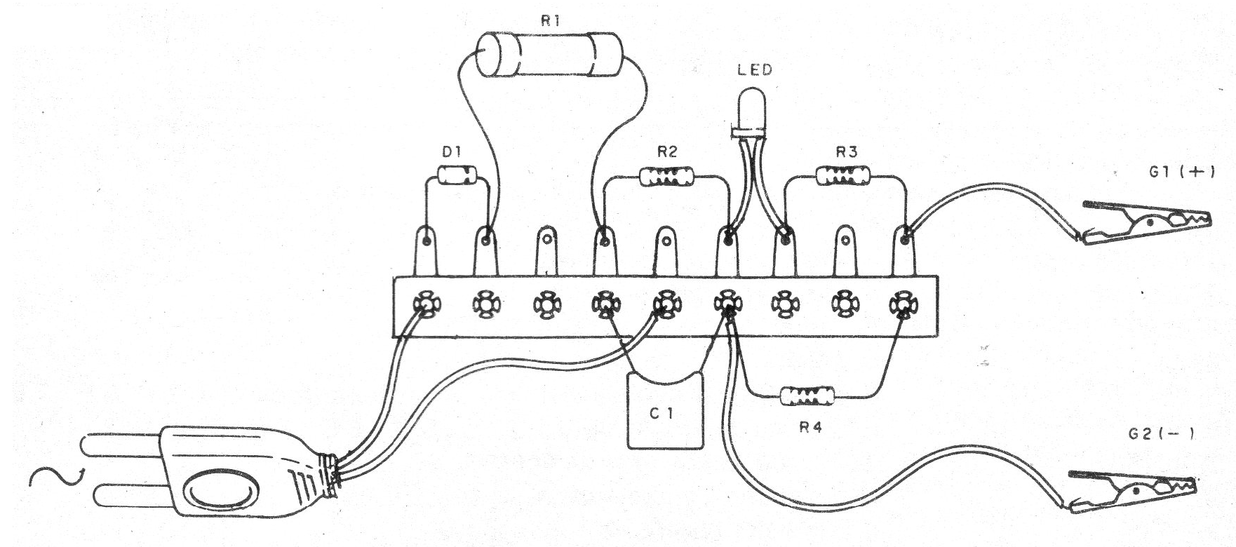
The assembly can be made based on a small terminal stgrip as shown in figure 3.
The resistor R1 is wire, and its value depends on the power grid.
The heat in brackets is for the 220 V mains, just as in the case of the diode.
On assembly, observe the diode and LED polarity.
The other components have specifications according to the bill of materials.
To connect the batteries to the load (which must be connected in series) use claw wires and a suitable holder.
Material list:
D1 - 1N4004 or 1N4007 - rectifier diode
LED1 - Common LED of any color
R1 - 2k2 ohms x 10 W (110 V) or 4k7 ohms x 10 W (220 V) - wire resistor
R2 - 10 k ohms - resistor - brown, black, orange
R3 - 100 ohms - resistor - brown, black, brown
C1 - 100 nF - 200 V (110 V) or 400 V (220 V) polyester capacitor
G1, G2 - alligator claws
Several:
Power cable, terminal strip, wires, solder, etc.


