
This small AM-range radio uses two Darlington transistors with enough power to power a small speaker. The radio is powered by 2 or 4 batteries and has good sensitivity.
Although medium-wave transmissions are expected to close soon, there are still many stations operating in this range, especially in small towns.
The receiver we describe has both didactic and recreational purposes, and can use scrap components.
This is the ideal assembly for a course of initiation to electronics.
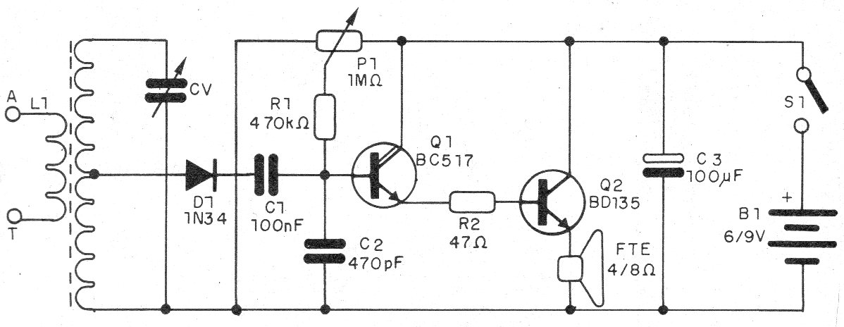
In this circuit we have a Darlington, with gain of more than 10 000 times for the signal.
The signal from this transistor is applied to a power transistor, with good signal strength to the speaker.
With this, small antennas can be used to capture local stations.
In figure 1 we have the complete diagram of the receiver of two transistors for the band of average waves.
As it is a didactic assembly we suggest the use of a terminal bridge, although a matrix version of contacts can also be adopted.
The arrangement of the components for the terminal strip is shown in figure 2.
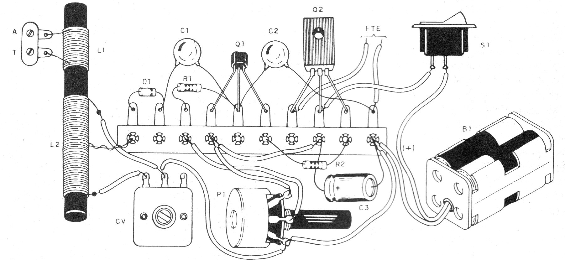
The coil is wrapped in a ferrite stick that can be harnessed from an old out-of-use transistor radio.
L1 consists of 20 turns of enamelled wire 28 to 30 and L2 of 30 + 70 turns of the same wire, as shown in the figure.
The variable capacitor can be harnessed from an out-of-use radio, as well as the small speaker and even some other components.
The resistors are 1/8 W with any tolerance and the capacitors conform to the bill of materials.
To test, connect an antenna (piece of wire from 2 to 5 meters) and ground connection, adjusting CV and P1 for best reception.
As the consumption of this radio is higher, we suggest the use of a small source of at least 300 mA.
Material list
Q1 - BC517 - NPN Darlington Transistor
Q2 - BD135 - medium power NPN transistor
D1 - 1N34 or equivalent - germanium diode
L1, L2 - Coils - see text
CV - variable capacitor - see text
S1 – On-Off switch
B1 - 3 or 6 V - 2 or 4 small batteries
FTE - 4 or 8 ohms - small speaker
P1 - 1 M ohms - potentiometer
R1 - 470 k ohms - resistor - brown, black, yellow
R2 - 47 ohms - resistor - yellow, violet, black
C1 - 100 nF - ceramic capacitor
C2-470 pF - ceramic capacitor
C3 - 100 uF x 6 V or more - electrolytic capacitor
Several:
Terminal strip, mounting box, battery holder, wires, solder, etc.


