
The purpose of this simple experimental circuit is to demonstrate the operation of an LED.
We use only 4 components, which allows experimental assembly in bridge bridges or in contact matrix.
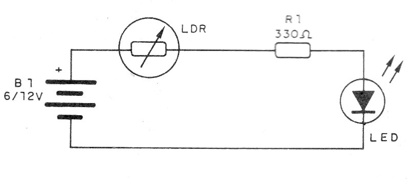
The idea is simple: when we illuminate the LDR it has its resistance reduced, letting pass a current that lights the LED.
When we shade over the LDR its resistance increases and the current in the LED decreases to the point where it shuts off.
In figure 1 we have the complete circuit of the experiment.
The arrangement of the components on a terminal strip is shown in Figure 2, although the circuit may also be bridge-mounted.
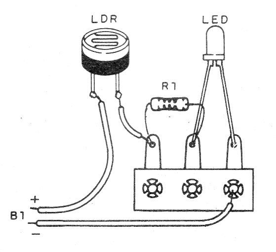
The LDR can be of any type and the polarity must be observed, because if it is inverted the circuit does not work.
To demonstrate, illuminate LDR: the LED should light up.
Covering the LDR, the LDR should shut down.
Material list
LDR - Common LDR
LED - any color LED
B1 - 6 or 12 V - batteries, power supply or battery
R1 - 220 ohms x 1/8 W - resistor - red, red, brown
Several:
Terminal bridge, wires, solder, etc.


