
This radio is so small that we can even mount it in a matchbox. Of course, due to the lack of amplification steps and the simplicity of the circuit, it presents some drawbacks that well demonstrate the difficulties encountered by radio pioneers.
Listening is only possible on a sensitive headset and you will still need to use a very long antenna, at least 10 meters long. This is because the energy that produces the sound in the headphones is the very energy captured by the antenna, which should be as large as possible.
However, in locations where there are strong AM stations, we can get a good listening of stations as long as they are not too far away.
It is, in fact, a modernized version of the old galena radios used by our ancestors in the early days of the radio. In this version the galena crystal is replaced by a germanium diode. In figure 1 we have the complete diagram of the radio.
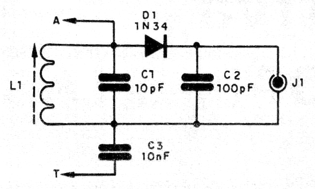
The clips A and T are connected to an antenna and earth. Earth can be any large metal object that has contact with the ground. The antenna is a conductive wire that can be wrapped, stretched. In figure 2 we have the receiver assembly.
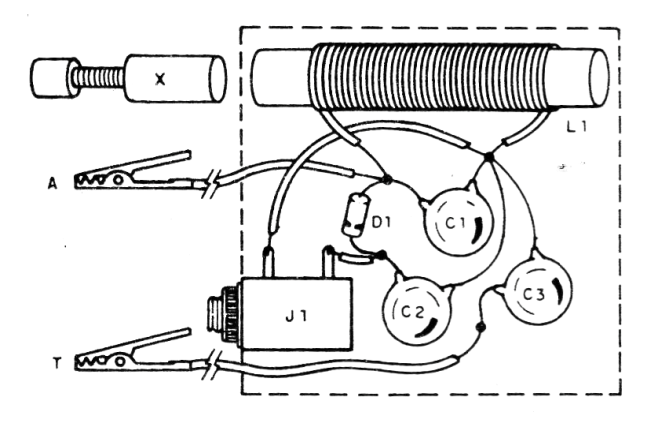
The coil L1 is formed by 100 turns of enameled wire 28 to 30 in a cardboard tube into which a small ferrite core can slide. This core can be obtained from IF coils from old radios. The movement of the ferrite makes the tuning of the station.
The capacitors C1, C2 and C3 are ceramic and the diode can be 1N34 or any equivalent of germanium.
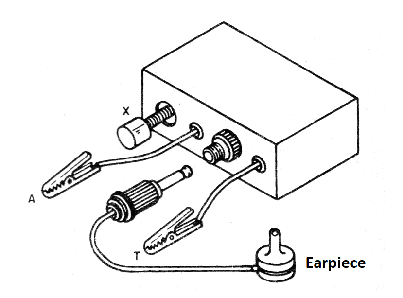
It is important to note that the handset must be made of crystal or a high impedance ceramic capsule. Most common headphones of the type used in MP3, Walkman and other devices are of low impedance. In figure 3 we have the suggestion of assembly in a small box.
Material list
L1-Coil - see text
D1- 1N34 - germanium diode
C1- 10 pF- ceramic capacitor
C2- 100 pF - ceramic capacitor
C3- 10 nF- ceramic capacitor
J1- Dial to the phone
Miscellaneous: mounting box, ferrite stick, enameled wires, crystal earpiece, etc.


