
Introducing a really good amplifier that delivers a power of 5W RMS (or 7W peak!) On an 8W speaker. The circuit uses only discrete components (transistors) and is therefore simple to assemble, constituting an excellent suggestion for technical courses and initiation to electronic technology.
The complementary symmetry configuration of this amplifier allows you to obtain excellent audio quality, especially if the loudspeaker used is heavy, good quality, mounted in a small speaker. By mounting two equal amplifiers you will have a stereo sound system with power similar to most 3-in-1 systems on the market.
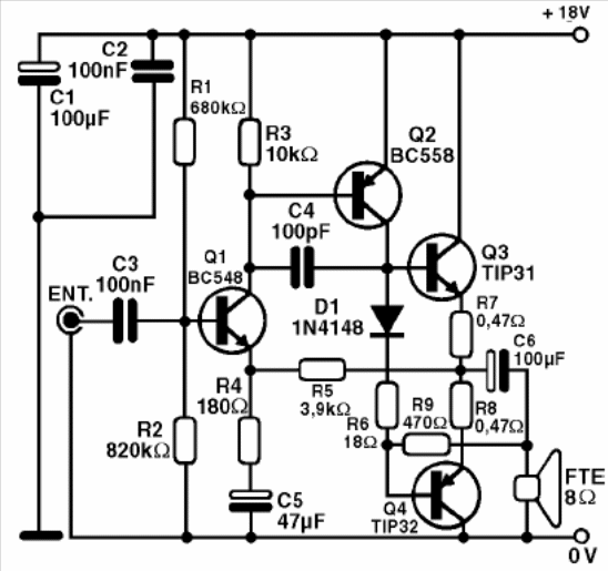
In figure 1, we have the complete diagram of the amplifier.
Since it is a matter of assembling many components and subject to buzzing, the arrangement of the components on a printed circuit board is important.
In figure 2 we have the assembly in PCB.
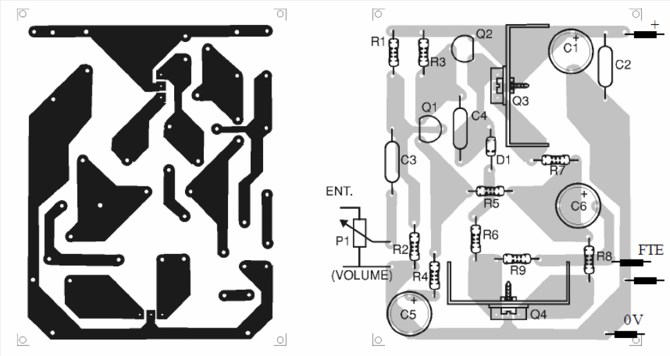
The radiators of the transistors consist of metal plates that are screwed into the body of the component. Radiators of this type can be purchased from specialist houses. For this amplifier it will be necessary to use a power supply whose diagram can also be seen in figure 3.
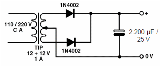
The transformer must have a secondary of at least 1 A with a voltage of 12 V and the diodes are 1N4002. The electrolytic should be 220 μF for better filtering, with a working voltage of 25 V.
In practice
If the sound card of your multimedia system requires an external amplifier (amplified box) you can use two amplifiers like this (one for each channel) for this purpose. Note that it will be important that used speakers are of good quality and installed in a small speaker.
One idea is to take advantage of that multimedia sound from your computer that no longer works, remove the original amplifier and connect it to the speaker. In fact, you can even use the sound output of your computer to excite this circuit, thus obtaining good sound quality.
Another application is as sound reinforcer for your small CD player or MP3. Your sound quality will be very good. You can also use it as a general purpose amplifier for your electronics stand.
MATERIAL LIST
Q1 - BC548 - NPN general purpose transistor
Q2 - BC558 - general purpose PNP transistor
Q3 - TIP31 - NPN power transistor
Q4 - TIP32 - PNP power transistor
FTE - 8W speaker
D1 - BA315 or 1N4148 - general purpose diode of silicon
C1 - 100 μF x 25 V - electrolytic capacitor
C2 and C3 - 100 nF - ceramic capacitor or polyester
C4 - 100 pF - ceramic capacitor
C5 - 47 μF x 25 V - electrolytic capacitor
C6 - 1 000 μF x 25 V - electrolytic capacitor
R1 - 680 kW x 1/8 W - resistor (blue, gray, yellow)
R2 - 820 kW x 1/8 W - resistor (gray, red, yellow)
R3 - 10 kW x 1/8 W - resistor (brown, black, orange)
R4 - 180 W x 1/8 W - resistor (brown, gray, brown)
R5 - 3.9 kW x 1/8 W - resistor (orange, orange, red)
R6 - 18 W x 1/8 W - resistor (brown, gray, black)
R7 and R8 - 0.47 x 1/2 W - resistor (yellow, violet, gold)
Miscellaneous: printed circuit board, heatsink for transistors, mounting box, wires, soldering.


