
This flasher for one LED, or Flasher, has an extremely low consumption, and can be powered by batteries or batteries, which will have enormous durability. The circuit operates with voltages from 3 to 12 V.
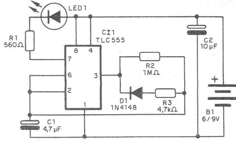
This circuit is based on the CMOS version of the well-known 555 which is the TLC555 or TL555 of very low consumption.
The circuit requires an average current of some micro-amps, which means a great durability for the batteries or batteries used in your power supply.
The frequency depends on C1 that can be changed over a wide range of values and the LED can be of any color.
In figure 1 we have the complete diagram of the pushbutton.
The assembly may be made in a contact array, or on a printed circuit board with the pattern shown in Figure 2.
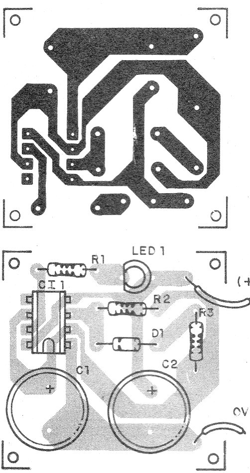
Note the position of the integrated, diodes and LED in the assembly.
Material list
CI-1 - TLC7555 (555 CMOS) - integrated circuit
D1 - 1N4148 - general purpose diode
LED1 - LED of any color
R1 - 560 ohms x 1/8 W - resistor - green, blue, brown
R2 - 1 M ohms x1 / 8 W - resistor - brown, black, green
R3 - 4k7 x 1/8 W - resistor - yellow, violet, red
C1, C2 - 10 uF x 6 V - electrolytic capacitor
B1 - 3 to 6 V - 2 to 4 batteries of any size
Several
Printed circuit board, battery holder, wires, solder, etc.


