
Using a built-in voltage regulator as a reference, we can control a variety of 2N3055 power transistors and thereby achieve stable high voltage output. For a 13.6 V output, this type of power supply is ideal for powering mobile communication equipment such as VHF and UHF transceivers for automotive use on a repair bench or for fixed use.
The circuit shown in figure 1 uses two 2N3055 transistors each controlling a current of 2.5 A which gives a maximum output value of 7.5 A. If the reader needs less current, you can use only one or two 2N3055.
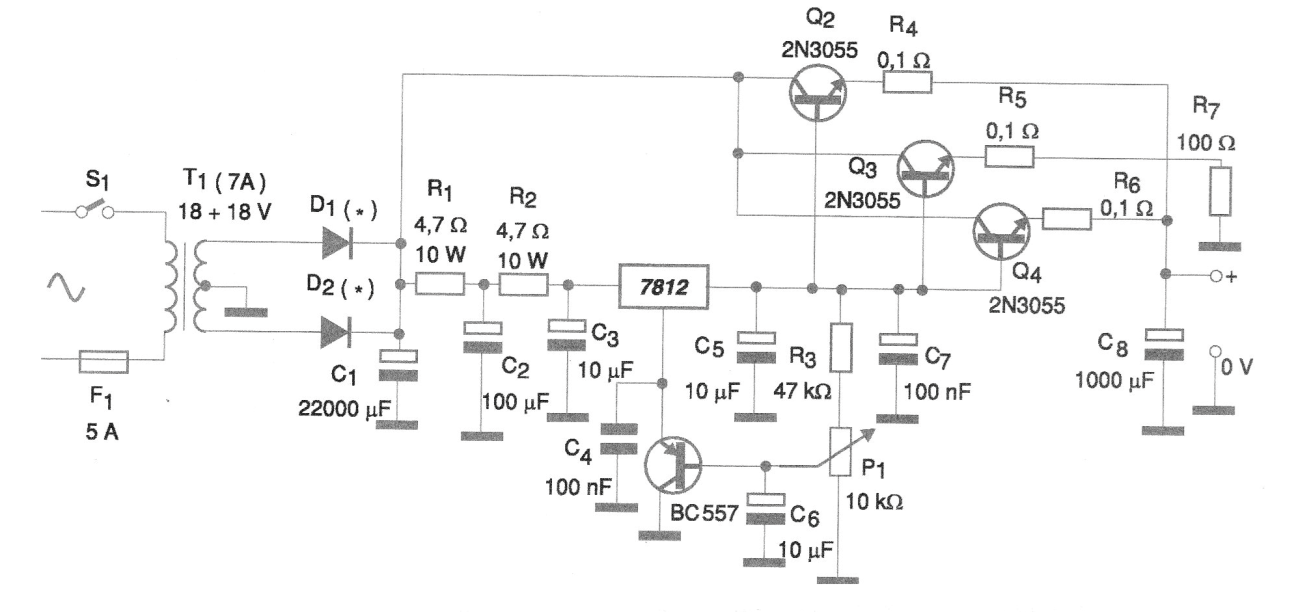
Note that at the emitter of each transistor we use a low-value wire resistor.
The purpose of this resistor is to ensure that the current is divided equally between all transistors, since in the conduction they have different resistance. Without them, the current would divide unevenly, possibly overloading one of the transistors it would then burn.
In assembling this type of source, the main care is to use wires of appropriate thickness to the current intensity to be driven. In figure 2 we show the layout of the assembly, observing that most of the components are external to the small printed circuit board that has the reference IC.
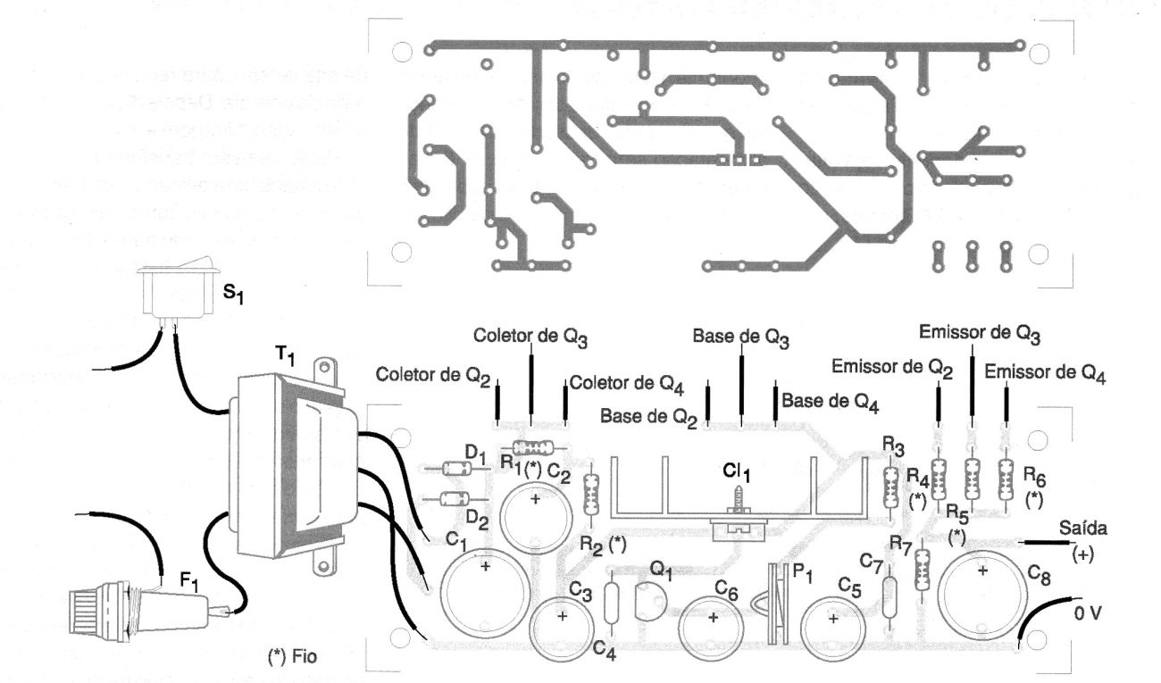
It is convenient to protect the circuit by fuses in both the input and the output.
It is also important to note that power transistors must be provided with excellent heat radiators. The integrated circuit 7812 also needs to be mounted on a heat radiator.
Resistors of 0.1 ohm and 4.7 ohm should be wire.
In the trimpot the output voltage can be adjusted to values between 12 and 13.6 V approximately.
Material list
CI-1 - 7812 - integrated circuit, voltage regulator
D1, D2 - 50 V x 10 A - Rectifier diodes
Q1 - BC557 - general purpose PNP transistor
Q2, Q3, Q4 - 2N3055 - NPN power transistor
T1 - Transformer with primary according to the local network - secondary 18 + 18 V with the maximum desired current at the output
F1 - 5 A - fuse
S1 – On/Off switch
C1 - 22 uF x 40 uF - electrolytic capacitor
C2 - 100 uF x 25 V - electrolytic capacitor
C3, C5 - 10 uF x 25 V - electrolytic capacitor
C4, C7-100 nF - ceramic capacitor
C6 - 10 uF x 12 V - electrolytic capacitor
C8 - 1000 uF x 16 V - electrolytic capacitor
R1, R2 - 4.7 ohm x 10 W - wire resistors
R3 - 47 k ohm x 1/8 W - resistor
R4, R5, R6 - 0.1 ohm x 2 W - wire resistors
R7 - 100 ohm 1 W - resistor
P1 - 10 k ohm - trimpot
Several:
Printed circuit board, heat radiators for transistors, mounting box, wires, solder, etc.


