
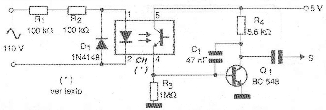
The isolated solution of the power grid of figure 1 allows a 60 Hz signal to be obtained from this network for the excitation of TTL logic circuits. The optical coupler used may be the TIL111 or any equivalent having a sensitive photo-transistor.
The resistors R1 and R2 are of ½ W and it is convenient to use two in series precisely so that the tension of the network divides between them. The C1 capacitor helps eliminate any transients that may distort the output signal frequency, which may be important in higher precision applications.
In very noisy environments this capacitor can be increased to 100 nF or even 150 nF.
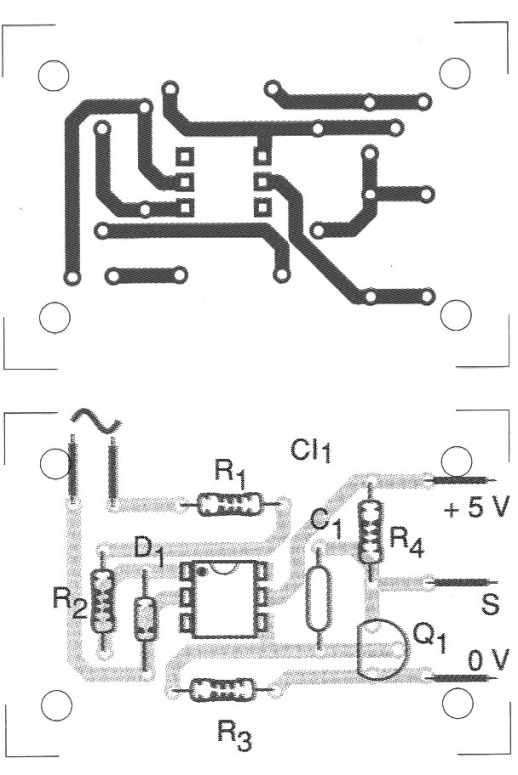
In figure 2 we have a printed circuit board suggestion for implementation of this time base. Note before assembly if the pinout of the optical coupler used is the same as indicated in this diagram.
MATERIAL LIST
CI-1 - TIL111 or equivalent - optical coupler
Q1 - BC548 or equivalent - NPN general purpose transistor
D1 - 1N4148 - general purpose diode
R1, R2 - 100 k ohm x 1W - resistors
R3 - 1 M ohm x 1/8 W - resistor
R4 - 5.6 k ohm x 1/8 W - resistor
C1 - 47 nF - ceramic or polyester capacitor
Several:
Printed circuit board, wires, 5V power supply, solder, etc.


