
If you have a small two-cell battery then this is a way to power it with a single 1.8V solar cell - a simple, good-performance converter. Operating with an alternating voltage that reaches 5V, we can even use a bender and get 6V, but with proportionally smaller currents.
The basic idea is simple: we convert the alternating current of the cell and apply to a transformer that doubles the voltage. Then just rectify and get at least 3 V for power to a radon.
As it is not possible to create energy, the current obtained at the end is much smaller than the maximum in normal conditions, nevertheless still enough to feed a two-cell battery at normal volume.
We tested the prototype with the National RF421OW radio from two large batteries and got its normal operation at medium volume when the power consumption was of the order of 10 mA.
OPERATION
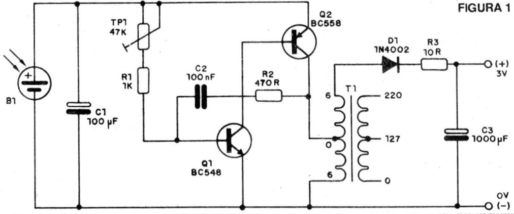
Two transistors are used in the oscillator configuration, already known for the good results presented and that have been extensively explored in our publications. The frequency of this oscillator is set to P1 in order to obtain the highest energy transfer efficiency. The setting will depend on the transformer.
We use an autotransformer which is actually obtained from a common power transformer with 6 + 6 V secondary and current between 100 and 500 mA. The highest voltage output is rectified by D1 and then filtered by electrolytic C3.
By connecting a voltmeter to C3 you will notice that the voltage can reach up to more than 5 V, but this is an uncharged peak value. With the radio connection or other load, the voltage will drop and this will depend on the consumption of the device.
We should then have a consumption that brings us close to 3 V, which will easily be achieved with a medium volume adjustment of a common radio. The degree of illumination of the cell directly influences the current obtained and in the case of a radio whose consumption is relatively high in view of the possible losses in the converter, it takes strong light.
ASSEMBLY
We begin by giving the complete diagram in figure 1.
In figure 2 we have the suggestion of mounting on a small printed circuit board.
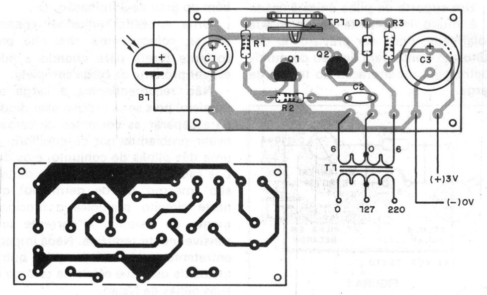
The adjustment trimpot P1 is not critical and may have values between 22k and 47k. The resistors are 1/8 W and the electrolytic capacitors have working voltages between 3 and 12 V.
The transformer T1 must have 6 + 6 V secondary with current between 100 and 250 mA. The primary, not being used, does not matter. Diode D1 may be of any type between 1N4002 and 1N4007. The transistors allow several equivalents such as: for the BC548 we have the BC237, BC238, BC547, BC549 and for the BC557 we have the BC307, BC308 BC558 and BC559.
TEST AND USE
For the test, simply plug in the output of a multimeter on the scale of continuous voltages that allows to read 3 V and illuminate the solar cell. For benchtop test use a 60 W lamp about 50 cm away from the cell.
Then set P1 to the highest possible voltage reading. The value will be higher than 3V because the capacitor will charge with the peak voltage obtained in the oscillator. With the radio on, this voltage will drop.
Turn on the radio to be powered using a power source jack, if any, or your claws attached to the battery holder (which should be removed). It is necessary to observe the polarity of this connection.
With cell illumination, the radio should operate normally with medium volume. Do not open the entire volume as there may be distortion. If the radio does not operate normally, check the voltage and set P1.
If nothing is still achieved, the problem may be in the transformer. If the voltage is too low on the radio, reduce the value of R3 or remove it from the circuit.
MATERIAL LIST
Q1 - BC548 - NPN transistor
Q2 - BC558 - PNP transistor
D1 - 1N4002 or equivalent - diode
B1 - 1.8 V x 500 mA - Solar Cell
T1 - 6 + 6V transformer - see text
P1 - 47k - trimpot
R1 - 1k - resistor (brown, black, red)
R2 - 470 ohm - resistor (yellow, violet, brown)
R3 - 10 ohm - resistor (brown, black, black)
C1 - 100 uF x 3 V - electrolytic capacitor
C2 - 1000 uF x 3V - electrolytic capacitor
Miscellaneous: printed circuit board, mounting box, wires, soldering etc.


