
With the circuit shown in figure 1 we can generate signals in the range of 30 to 150 MHz, which can be very useful in the test and adjustment of receivers, in the determination of sensitivity to interference in this range by telecommunications equipment or even in a small link to the VHF band.
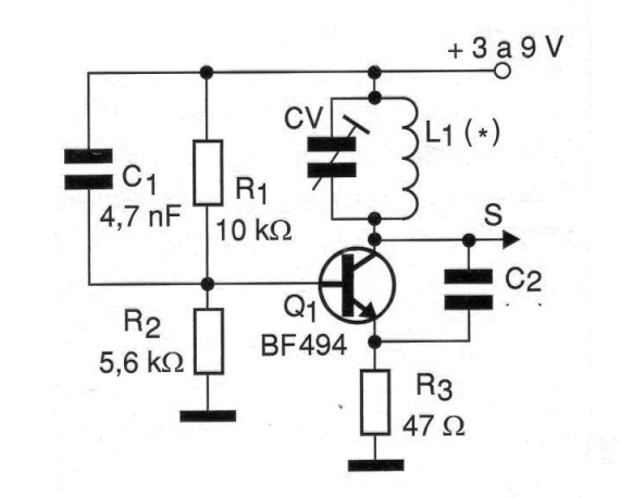
Modulation, if necessary, can be done by applying the modulating signal to the base or emitter of the transistor, depending on its amplitude. The operating frequency depends on the coil that can be wound with enameled wire from 18 to 22 AWG in the form of 1 cm in diameter without core as per the following table:
| Frequency range
|
|
| Number of turns | |
| C2 | |
| 30 – 50 MHz
|
|
| 7 to 10 | |
| 22 pF | |
| 50 a 80 MHz
|
|
| 4 to 6 | |
| 10 pF | |
| 80 a 120 MHz
|
|
| 3 to 4 | |
| 4,7 pF | |
| 120 a 150 MHz
|
|
| 1 to 2 | |
| 1 a 2 pF |
Note that the value of C2 also depends on the frequency range.
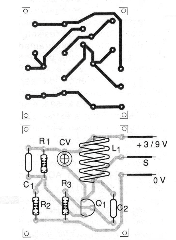
The transistor can be the BF494 or equivalent and all capacitors must be ceramic of good quality. For fine adjustment of frequencies the trimmer can have values between 5 and 20 pF of maximum capacitance. In figure 2 we have a suggestion of printed circuit board for the assembly of this circuit.
MATERIAL LIST
Q1 - BF494 or equivalent - RF NPN transistor
R1 - 10 k ohm x 1/8 W - resistor - brown, black, orange
R2 - 5.6 k ohm x 1/8 W - resistor - green, blue, red
R3 - 47 ohm x 1/8 W - resistor - yellow, violet, black
C1 - 4.7 nF - ceramic capacitor
C2 - 1 to 10 pF - see text
CV - trimmer from 5 to 20 pF of maximum capacitance
L1 - Coil - see text
Several:
Printed circuit board, wires, solder, etc.


