
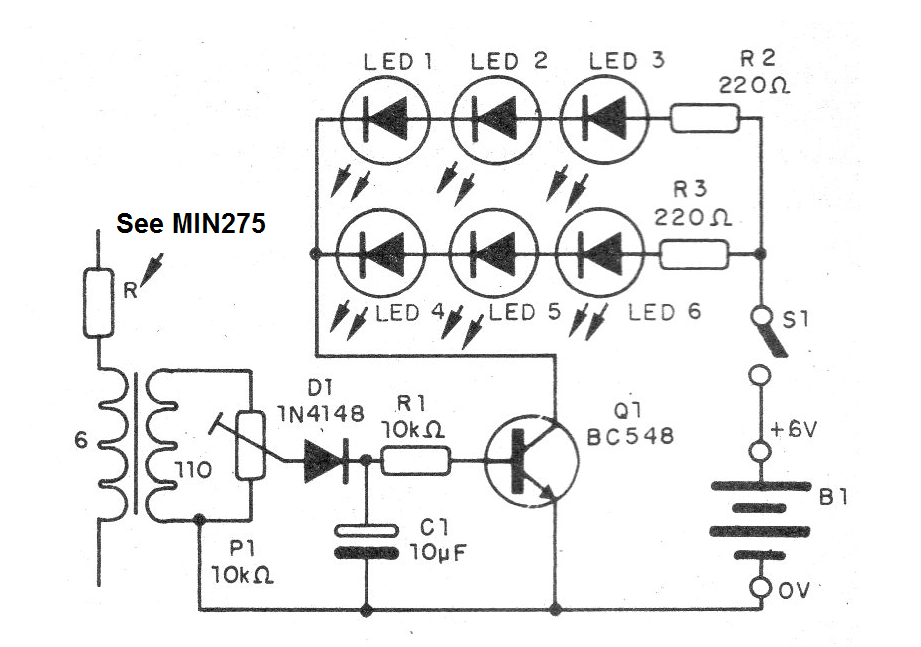
Unlike the case of the rhythmic LED I will have the blink of many and not only 1.
The circuit requires an external source and the transformer is of the same type used in the design of the Rhythmic LED I.
The potentiometer is used to adjust the point at which the LEDs start flashing.
In figure 1 we have the diagram of the rhythmic LED system II.
The assembly can be made on the basis of terminal strips as shown in figure 2.
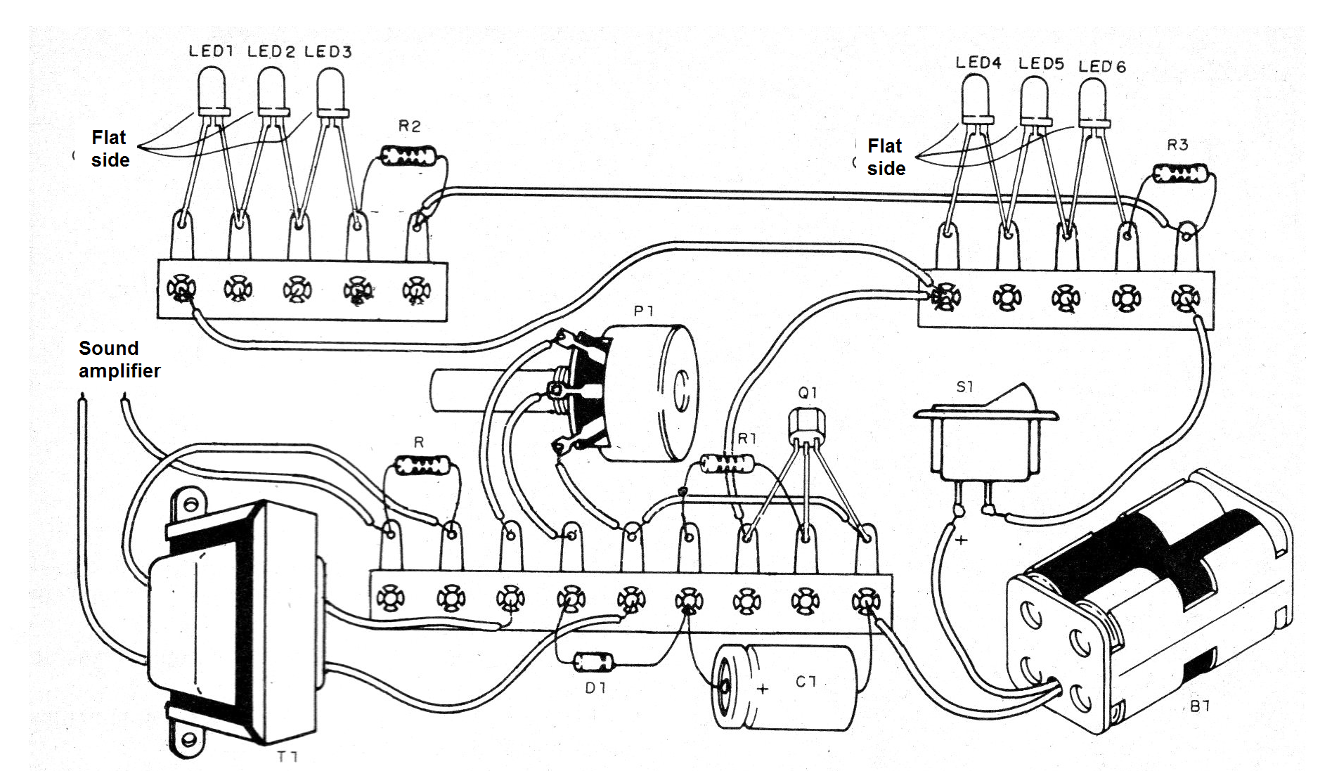
The LEDs can be of different colors in each series.
R3 is as indicated in the MIN535.
Material list
Q1 - BC548 - NPN general purpose transistor
D1 - 1N4148 - general purpose diode
LED 1 to LED6 - Common LEDs
T1 - Transformer with 110 V primary and 6 V secondary
P1 - trimpot or potentiometer of 10k
R1 - 10 k ohms x 1/8 W - resistor - brown, black, orange
R2, R3 - 220 ohms x 1/8 W - resistors - red, red, brown
S1 – On-Off switch
B1 - 6 V - 4 batteries
Several:
Terminal strip, battery holder, wires, solder, etc.


