
The sound produced by this siren varies in frequency at a pace that can be adjusted. The circuit can be used in alarms, warning systems and sound effects in shows.
The output power of this siren is high, and bipolar transistors can be used for 6 to 12 V supply.
For this case, we can use the TIP31 with a base resistor of 1 k ohms.
The circuit has three settings that lead to the desired tone with ease.
The combination of these settings can generate sounds of many different types.
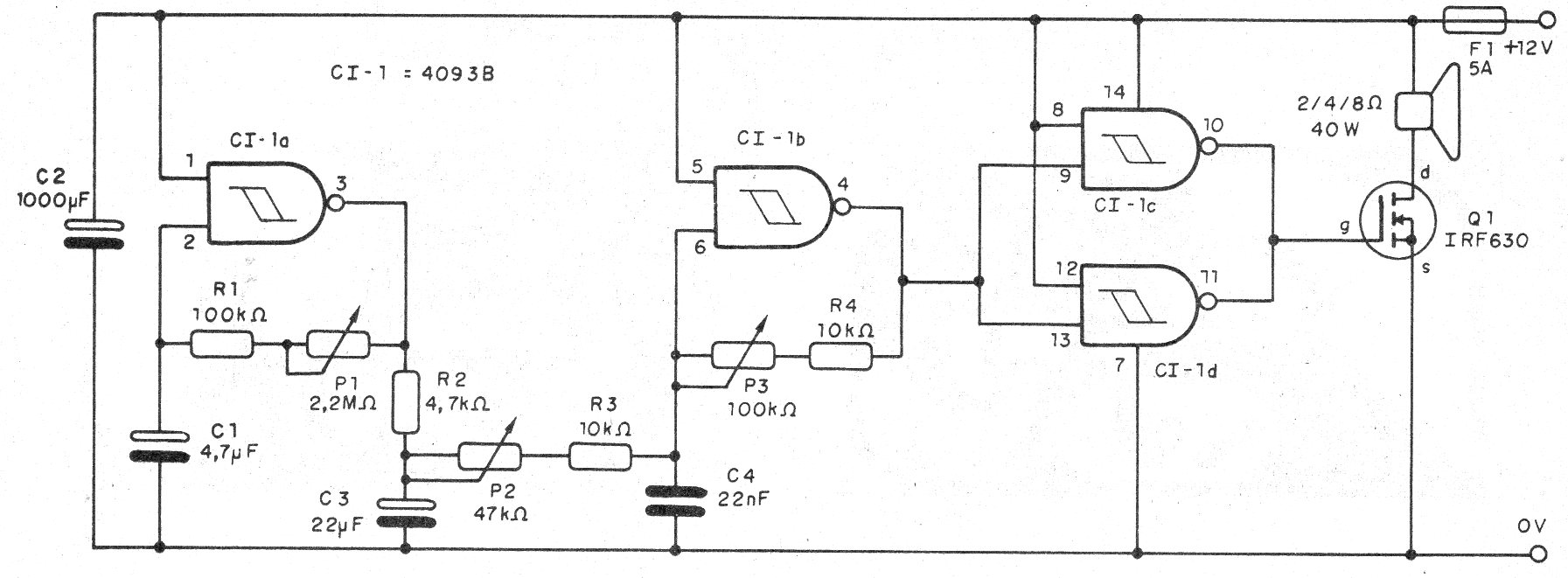
The basis of the design is a 4093 integrated circuit consisting of four trigger ports.
The first port is used as a slow oscillator for the modulation circuit, set at P1.
The signal from this port passes through an effect circuit that has its charge and discharge constant set at P2.
This circuit determines how the modulation of the oscillator circuit is made.
To generate the modulated tone the second port of the 4093 is used, with the base frequency set at P3.
The signal from this oscillator is digitally amplified by the remaining two ports of the 4093 and is applied to a power MOSFET.
As a load, the MOSFET has a loudspeaker which, for greater efficiency, must be of the heavy type.
In figure 1 we have the complete diagram of the siren.
A printed circuit board for the assembly is shown in figure 2, taking the MOSFET version as reference.
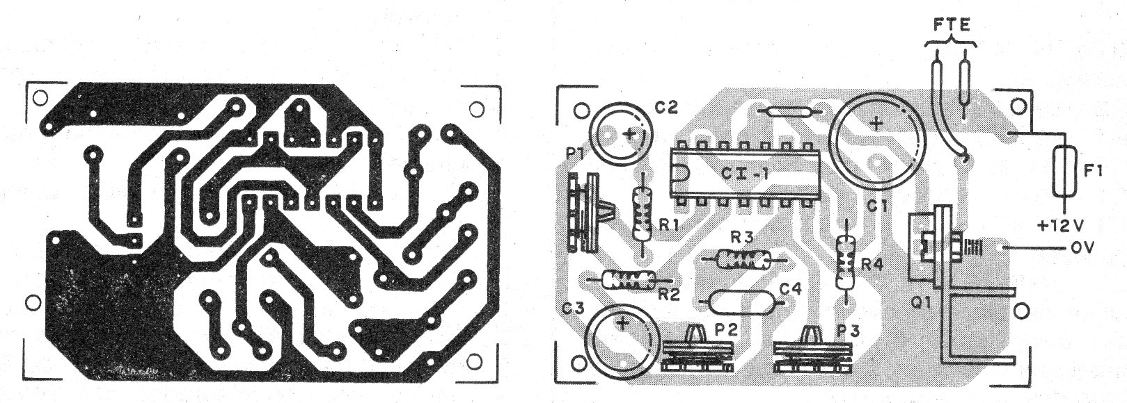
The transistor must be provided with a heatsink and n assembly, observe its position, as well as the integrated circuit.
Material list
CI-1 - 4093 - integrated circuit
Q1 - IRF640 or equivalent - see text
P1 - 2M2 ohms - trimpot
P2 - 47 k ohms - trimpot
P3 - 100 k ohms - trimpot
R1 - 100 k ohms - resistor - brown, black, yellow
R2 - 4k7 ohms - resistor - yellow, violet, red
R3, R4 - 10 k ohms - resistors - brown, black, orange
C1 - 4.7 uF - electrolytic
C2 - 22 uF - electrolytic
C3-22 nF - ceramic or polyester
C4 - 1000 uF - electrolytic
FTE - 2 or 8 ohms - speaker
F1 - fuse 2 A
Several:
Printed circuit board, heat radiator, mounting box, wires, solder, etc.


