
The second version of a photoelectric control for a DC motor (by light) using a Darlington transistor is shown in figure 1.
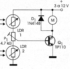
In this case, the high gain of the transistor used allows it to be excited directly by the LDR without the need for additional steps of amplification.
An important feature of this circuit is its differential operation with two sensors, which allows its use in interesting applications. The use of two sensors causes the circuit to have four possible modes of operation:
a) Two LDRs in the dark - motor stands still
b) The LDR 1 receives light and the LDR2 remains in the dark - the motor is started
c) The LDR 1 is lit when the engine is running and the LDR2 is in the dark. When the LDR2 gets enough light, the motor is cut (stops)
d) The LDR 1 is dimly lit and the LDR2 illuminated. When the light on the LDR2 is cut off, the engine starts to run.
e) The two LDRs are illuminated - depending on their intensity and P1 setting the motor may or may not work.
Among the possible applications for this circuit is a robot that can make decisions depending on the light that it "sees" through the sensors (LDRs).
In figure 2 we have the assembly of this circuit in a terminal strip that is the version indicated to the readers less experienced and with fewer resources.
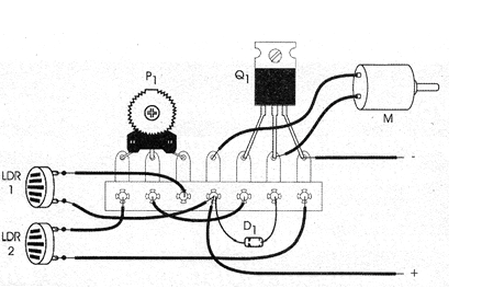
For those who wish, it is possible to mount the printed circuit board or matrix of contacts.
For motors above 200 mA it will be convenient to provide the transistor with a heat radiator. The operating point setting will be done on the trimpot.
Material list
Q1 - TIP110 or equivalent - Darlington NPN Power Transistor
D1 - 1N4148 - general purpose diode
LDR1, LDR2 - Common LDRs
P1 - 4.7 k ohms (or greater) - trimpot or potentiometer
M - 3 and 12 V common motor
Several:
Terminal strip, 3 to 12 V supply, heat radiator for transistor, wires, solder, etc.


