
You can control a light bulb, a motor or an appliance in the distance with the focus of a flashlight. Simply point the flashlight at the sensor and activate it as the light incident on the sensor triggering the circuit.
Many interesting and useful applications can be found for this system. One would be a game in which you would be hidden away and could make a fan, lamp or another device which turns on by itself.
The circuit is only for resistive loads like lamps and motors, and should not be used to control electronic devices such as stereos, televisions, etc. In Figure 1, we have the complete diagram of the control.
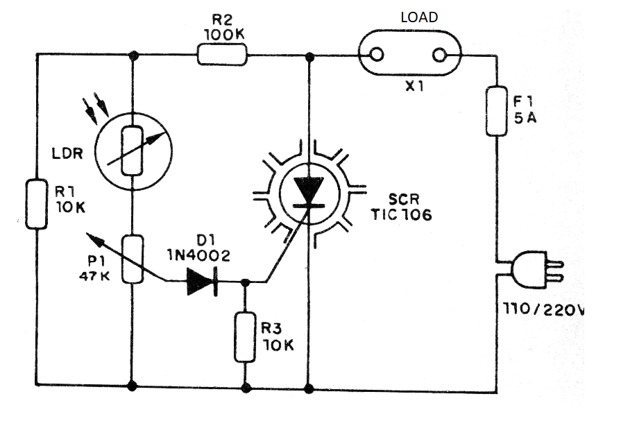
Note that this circuit is half-wave, which means that the load fed operates at half the power. TIC106 should have the suffix B if the network is 110 V and D if the network is 220 V. The maximum load is 3 and the SCR must be provided with heat radiator. In Figure 2, we have the assembly on a terminal strip.
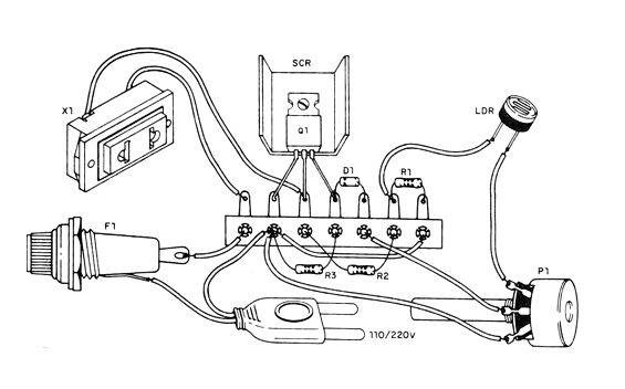
The LDR can be of any type. Be careful, as the device is not isolated from the power supply, and may cause shocks to those touching the exposed parts.
Note that the controlled device stays on only as long as there is light striking the sensor. With the light cut off the load turns off.
Material list
SCR-TIC106B (110 V) or TIC106D (220 V) - silicon controlled diode
D1- 1N4002 or 1N4004 - silicon diode
LDR-LDR common rounded
P1-47k - potentiometer
R1, R3 - 10k ohms x 1/8 W- resistors - brown, black, orange
R2- 100 k ohms x 1/8 W- resistor - brown, black, yellow
F1- 5 A fuse
X1 - Outlet
Miscellaneous: terminal bridge, SCR heat radiator, power cable, mounting box, wires, welding, etc.


