
This circuit has a different characteristic: it uses the capacitance of the ceramic transducer itself to determine the frequency of operation. The circuit, simple to assemble, can be used for experimental or didactic purposes.
Unijunction transistors are no longer widely used, but still serve many experimental and didactic projects involving the generation of sounds or low frequencies.
The circuit shown is of a relaxation oscillator whose frequency depends on the setting of P1 and the capacitance of the transducer.
The highest sound intensity occurs when the circuit can be adjusted to the resonant frequency of the transducer.
The circuit can be powered by voltages between 6 and 12 V.
In figure 1 we have the complete diagram of the oscillator.
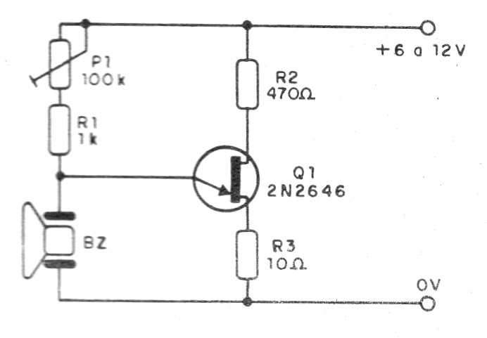
It may be necessary in some cases to connect a capacitor from 1 nF to 22 nF in parallel with the transducer if it does not oscillate.
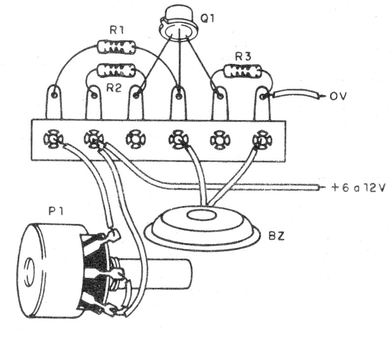
In figure 2 we have a suggestion for the assembly using a small terminal bridge.
For didactic purposes it will be interesting to use an solderless board.
Material list
Q1 - 2N2646 - unijunction transistor
BZ - ceramic transducer (piezoelectric capsule)
B1 - batteries or power supply - 6 to 12 V
P1 - 100k ohms - potentiometer
R1 - 1k ohms x 1/8 W - resistor - brown, black, red
R2 - 470 ohms x 1/8 W - yellow, violet, brown
Several:
Terminal bridge, wires, solder.


