
An integrated transistor provides this receiver with excellent sensitivity for reception of local mid-wave stations with voltages as low as 1.2 V and is an ideal design for powering with alternative sources, including our solar cell.
The circuit was originally designed to operate with a 1.2 V cell, but will work with any one up to 3.0 V. The ZN414 (Component not very common in our market today) is a dedicated integrated circuit consisting of a full-featured mid-range radio (150 kHz to 3 MHz) for low voltage power and is ideal for ultra-compact or alternative power projects.
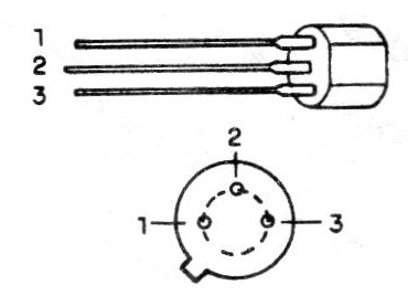
In fact, the ZN414 enclosure is the same as the well-known BC548 transistor, even with three terminals only, which makes it possible to use them in amazing projects like the one we give. (figure 1)
Radios on key chains and watches or even built-in headphones can be made simply with this integrated one that includes a FET input stage and several high-gain amplifier inputs.
Our project aims to take advantage of the low voltage of the solar cell in a medium-wave receiver that can be used in emergency situations.
With the ZN414 as a base and we can achieve this with ease we have the advantage of not needing an external antenna and good sensitivity combined with good selectivity.
The features of the ZN414 are:
- Voltage supply range: 1.2 / 1.6 V
- Power supply: 0.3 mA (typical) and 0.5 mA under strong signals
- Operating frequency range: 150 kHz to 3 MHz
- Input resistance (tip): 4M
- Sensitivity with 1.3 V power supply: 50 uV
- Audio distortion: less than 2%
- The Selectivity: 4kHz
- Power gain: 72 dB
- Output: 30 mV rms
HOW IT WORKS
The ZN414 is a complete receiver requiring very few external components to operate. These components are basically the tuning circuit formed by a coil (L1) and a variable (CV), a bias resistor and a decoupling capacitor. At the output we simply need a load resistor and a decoupling capacitor.
As the output is of very low intensity, this configuration can only excite a crystal earphone, as in the circuit of figure 2.
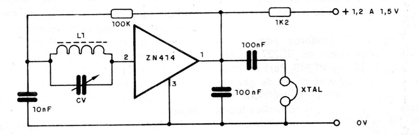
However, even this circuit is low volume, so that with a little more power available, we can add a transistorized amplifier stage.
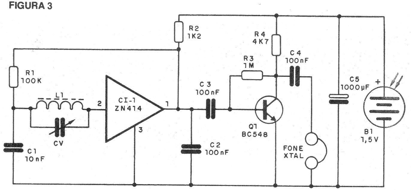
In our case, we use a single general purpose NPN transistor that increases the sound intensity (approximately 500 gain) by getting better sound from the handset. Since the transistor is a medium output impedance device we can not still excite a speaker.
The recommended handset is glass. Other types of headphones will not work. The current consumption of this radio is very low, which allows the use of a cell even with relatively small levels of illumination.
ASSEMBLY
We begin by giving the complete diagram of the radio in figure 3.
The very compact printed circuit board is shown in figure 4.
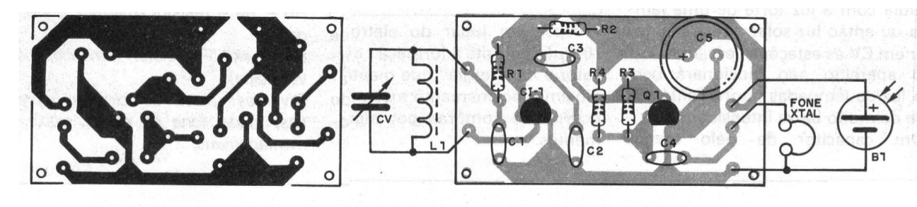
L1 consists of 80 turns of wire 30 in a ferrite rod 5 to 1mole in length with a diameter of between 0.5 and 1 cm. The variable is common for medium waves with 180 to 360 pF. The resistors are 1/8 and 1/4 W and the capacitors are ceramic disk. The transistor may be any generally good NPN with good gain, such as BC238, BC239, BC548 or BC549.
The source electrolytic for filtering any noise is 1000 uF x 3V or more. The handset must be of crystal, as another type will not work.
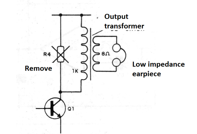
Eventually, with a lower gain, a low-impedance (walkman type) handset with an output transformer of at least 1k of primary, connected as shown in figure 5, may be used instead of the collector load resistor of the transistor.
OPERATION
To use the radio, simply illuminate the cell with the strong light of a light bulb or direct sunlight and tune to CV the desired stations. The unit will not work well with fluorescent lamp or very low light source.
A capacitor of at least 4700 uF, instead of the electrolytic of 1 000 uF, allows the formation of a "power reservoir" that will keep the radio operating even when shadows occur for a few moments.
MATERIAL LIST
CI-1 - ZN414 - integrated circuit - (radio)
Q1 - BC548 or equivalent - NPN transistor
L1 - coil (see text)
CV - variable (see text)
B1 - 1.8 V solar cell X 500 mA
C1 - 10 nF - ceramic capacitor
C2, C3 - 100 nF - ceramic capacitors
C4 - 47 to 100 nF - ceramic capacitor
C5 - 1000 uF .x 3 V - electrolytic capacitor
R1 - 100k - resistor (brown, black, yellow)
R2 - 1k2 - resistor (brown, red, red)
R3 - 1 M - resistor (brown, black, green)
R4 - 4k7 - resistor (yellow, violet, red)
Various: printed circuit board wires, solder, crystal earphone, box for mounting etc.


