
With the use of a transistorized amplifier stage the small variations of resistance of the thermistor are detected taking the circuit to the trigger point. The setting of this trip point is given by the trimpot connected to the comparator reference input. For greater precision a multi-turn trimpot must be used.
The relay used is of the sensitive type with a coil of 50 mA at the maximum and voltage according to the one used in the power supply.
If the sensor is somewhat distant from the circuit (more than 2 meters), shielded cable must be used with properly grounded mesh. The 100 nF capacitor at the thermistor input prevents transients or short pulses from causing the circuit to trip erratically.
The power supply must be stabilized so as not to affect the trip point of the circuit. One possibility that can be analyzed for some applications is the use of a common diode inversely polarized as a temperature sensor.
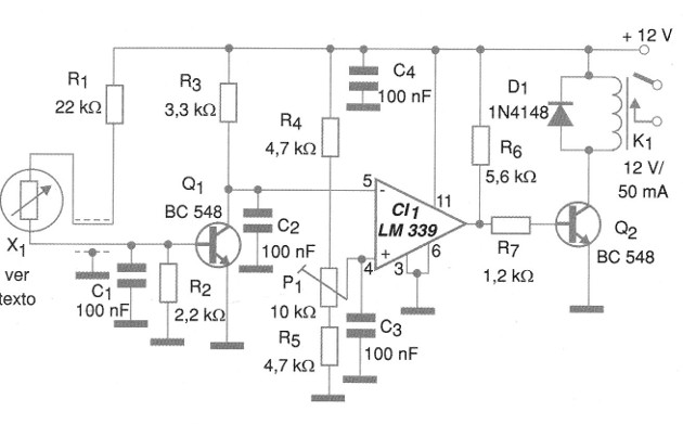
Semiconductors:
CI-1 - LM339 or equivalent - used - comparator
Q1, Q2 - BC548 - general purpose NPN transistors
D1 - 1N4148 - general purpose diode
Resistors: (1/8 W, 5%)
R1 - 22k ohms
R2 - 2.2 k ohms
R3 - 3.3 k ohms
R4, R5 - 4.7 k ohms
R6 - 5.6 k ohms
R7 - 1.2 k ohms
P1 - 10 k ohms - trimpot multivolt
Capacitors:
C1, C2, C3, C4-100 nF - ceramic or polyester
Several:
X1 - Thermistor - see text
K1 - 12 V x 50 mA Relay
Printed circuit board, shielded wires, power supply, welding, etc.


