
To get an idea of what a microcontroller design can be, without using Unified Modeling Language (UML) or a similar method, it can be compared to someone who wants to build a building and does not use an architect to shape the project.
We can also compare it to who wants to make a mechanical part and does not make a plan, drawing or diagram of this part. It can be said that the UML language is like the architecture or plan of a microcontroller project.
Initially the language was created to be able to develop software programs and projects for computers, but nowadays it is being used to develop programs or projects with microcontrollers. As the UML language was developed for object-oriented languages (classes) such as C++/C # and most of the microcontroller projects are written in C language, it is necessary to make some adaptations to support UML in C language.
The UML language is formed by a series of diagram for the purpose of describing, organizing, formatting, classifying, etc. the project to be developed. In the case of projects with microcontrollers, the most used diagrams are:
Use Case Diagrams.
Class Diagrams.
State Diagrams.
In this article we will explain how to use these diagrams in the development of a project or idea which uses microcontrollers.
USE CASE DIAGRAM
The use case diagrams indicate the uses which the project can have, that is, what the project is for and who will use them. For this reason, this diagram has two important components.


Users are represented in the diagram by a symbol similar to the one given in Figure 1. The Use Cases are represented in the diagram by a symbol similar to the one in Figure 2. Next to the symbols Users it is placed a text describing their role and within the symbols Use Cases it is placed a text describing its function.

Figure 3 shows an example Case of Uses diagram for a design of a basic car alarm. In this diagram, the line with arrow indicates that the User (actor) makes use of the project.
CLASS DIAGRAM
The Class Diagrams describe the functions and data (variables) of the project. This diagram is in charge of classifying the functions (routines) in modules or blocks for a better organization of the software. These modules or blocks are called Classes.
Each Class in the diagram is formed by 3 main parts:
1- Class Name.
2- Properties or variables.
3- Functions or Routines
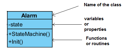
Figure 4 describes the points where each part of a class is placed. The class name should indicate to whom variables and functions are oriented. For example, in an alarm, this class can be called Alarm. Variables are the data required for the module or class to work.
These variables can be organized into a structure. For the Alarm class this structure is encoded in the header file (alarm.h) and is as follows:
typedef struct
{
uint32_t state;
}Alarm;

Functions are codes organized by routines. Figure 5 shows an example of a class diagram for a car alarm. From this diagram we can generate the code for each class. For example, for the Alarm class we have:
#include "Alarm.h"
Alarm a;
******************************************************************/
void Alarm_StateMachine(Event event)
{
}
******************************************************************/
void Alarm_Init(void)
{
}

Similar codes are generated for the other classes. Figure 6 shows the block diagram for a basic car alarm. It may be noted that there is a relation between the blocks and the classes in the diagrams. This is an orientation, but depending on the project we can have more classes.
STATE MACHINE DIAGRAM
This diagram describes the dynamic operation of the project, i.e., how the project should work. This diagram is formed by the following symbols:
1- States.
2- Transitions.
3- Events.
4- Actions.


In Figure 7 we have the symbol for the States. Figure 8 shows the symbol for the transitions. Figure 9 shows the Events, being names (texts) which are placed next to the transitions. Figure 10 shows the Actions, which are routines or functions of the class diagram.

switch(a.state)
{
case Alarm_Disarmed:
break;
case Alarm_Armed:
break;
case Alarm_Triggered:
break;
}
Once the state diagram is drawn, it is necessary to do its coding. For this, a case is pointed out in a switch instruction. The code for the state diagram in Figure 11 is:
case Alarm_Disarmed:
switch(event)
{
case BUTTON:
a.state = Alarm_Armed;
break;
}
break;
Now, in each case corresponding to each state is necessary to treat the events that this state can handle. For example, for the Alarm_Disarmed state, the events are:
case Alarm_Disarmed:
switch(event)
{
case BUTTON:
a.state = Alarm_Armed;
break;
}
break;
For the Alarm_Armed state the handled events are:
case Alarm_Armed:
switch(event)
{
case BUTTON:
a.state = Alarm_Disarmed;
break;
}
break;
For the Alarm_Triggered state the handled events are:
case Alarm_Triggered:
switch(event)
{
case DOOR_OPEN:
Siren_On();
a.state = Alarm_Triggered;
break;
case ULTRASONIC:
Siren_On();
a.state = Alarm_Triggered;
break;
case BUTTON:
a.state = Alarm_Disarmed;
break;
}
break;
This form of codification is called the State Machine. Next, you need to merge all of this code and a single function to create the project state machine. The function will be:
******************************************************************/
void Alarm_StateMachine(Event event)
{
switch(a.state)
{
case Alarm_Disarmed:
switch(event)
{
case BUTTON:
a.state = Alarm_Armed;
break;
}
break;
case Alarm_Armed:
switch(event)
{
case BUTTON:
a.state = Alarm_Disarmed;
break;
}
break;
case Alarm_Triggered:
switch(event)
{
case DOOR_OPEN:
Siren_On();
a.state = Alarm_Triggered;
break;
case ULTRASONIC:
Siren_On();
a.state = Alarm_Triggered;
break;
case BUTTON:
a.state = Alarm_Disarmed;
break;
}
break;
}
}
For both states and events it is necessary to create enumerators (enum) so that the code in the Alarm.c file recognizes these names. This is done on the header file, i.e., in Alarm.h. The code is:
enum ALARM_EVENTS
{
BUTTON,
DOOR_OPEN,
ULTRASONIC
};
enum Alarm_State
{
Alarm_Disarmed,
Alarm_Armed,
Alarm_Triggered
};
The main.c file for the car alarm project will then be:
#include "Alarm.h"
#include "RemoteControl.h"
#include "Ignition.h"
#include "Door.h"
#include "UltraSonic.h"
#include "Siren.h"
int main()
{
Init_IO();
Alarm_Init();
RemoteControl_Init();
UltraSonic_Init();
while(1)
{
RemoteControl_Events();
Ignition_Events();
Door_Events();
UltraSonic_Events():
}
}
Note in the main loop the call to the Events () functions of each class. And in this function or routine where the events for the project are coded. The following code shows an example for the Door class.
******************************************************************/
void Door_Events(void)
{
if( Door_IsOpen() )
{
Alarm_StateMachine( DOOR_OPEN );
}
}
So for any door of the car that is opened the Alarm_StateMachine () function is sent to the DOOR_OPEN event and the state machine is in charge of processing the event according to the state in which it is.
The example in this article is simple, but demonstrates how to use the UML diagram to create a microcontroller project. In a real project, you can usually use more functions such as locking the car doors, raising the door windows if they are open, or locking the car if it is stolen.
There are programs to edit UML diagrams. Some examples are: Visual Paradigm, Enterprise Architect, Microsoft Visual Studio, and many others, but Figure 12 shows the class diagram editor of the Visual Paradigm program. These programs are easy to use and very intuitive in their handling.


