Features
Transmitter: any 10 to 100 W audio amplifier
Range: up to 1 mile (depending on the amplifier power and the antenna)
Frequency range: audio (16 to 16,000 Hz)
Technology: low-frequency current field
During World War II, when German troops occupied France, French radio amateurs were prohibited from using their radio systems. But communication was very important to the “resistance,” as they needed to disseminate important messages.
The French radio amateurs soon discovered that, even if the “air” couldn’t be used to send messages, the Earth could provide an excellent substitute. It was enough to place two electrodes into the ground and connect them to the output o any audio amplifier. The current field produced by this system could be picked up by two distant electrodes, with the transmitted signal reproduced in an earphone.
Using amplifiers with powers in the range of 10 to 40 W, it was possible to send messages over distances up to several miles.
This very simple transmission system has many drawbacks, as the signals are not tuned, and the electrodes must be placed as far as possible from each other.
However, the reader can use it for conducting experiments or to build a short-range communication system.
The principal advantage is that the signal can”t be picked up by common radio receivers and causes no interference to other communication systems. If you use two audio amplifiers, a bilateral communication system easily can be built.
How It Works
The system is based on “current fields.” If we place two electrodes in a homogeneous conductor such as the Earth, as shown in Fig.1, and apply a voltage between them, a current field will be produced.
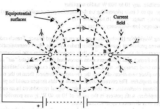
The current flowing between the electrodes will be distributed by field lines (as in a magnetic field). If we place two electrodes across these lines, a voltage will be detected with a value that depends on their separation along the particular line.
Notice that, between different lines, it is possible to draw an imaginary line along which all of the voltages are equal. This is called the equipotential surface, as it is not really a line but a surface (as shown in Fig. 1).
The reader, from this explanation, can easily see that, if we place two electrodes at a convenient location along the current field, it is possible to pick up the signal. Even if the electrodes are placed very far away from the transmitter (current source), a small voltage can be picked up.
In theory, the electrodes can be placed at distances as far as infinity, but the practical sensitivity of the receiver will limit this distance to a few hundred feet up to several miles.
At a great distance from the transmitter, the voltage will be overwhelmed by other induced signals existing in the ground, such as hum, atmospheric discharges, and many other noise sources.
For direct current and low-frequency signals, the principle is valid as described. But as frequencies rise, other factors begin to act on the current fields.
For high-frequency signals, attenuation increases, and wave propagation in the air becomes more important than the current fields in the Earth.
To obtain the best performance from a system like this, it is important to consider some technical facts. First of all, if you plug the output of any ampliúer into the ground, the audio-frequency signal must be completely transferred, which means that you must establish a correct impedance match. The groundºs impedance depends on several factors, including the distance between the electrodes, the electrodes, size, and the type of soil in which the electrodes are placed. This impedance can range from several Ω to hundreds of Ω.
The best away to match the ampliúer output impedance with the soil impedance is via the use of a transformer as shown in Fig. 2.
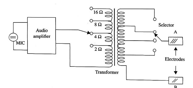
A transformer with several taps can be used to find the best impedance match for an Earth communication system. The electrodes used as “antennas” must be as far apart as possible. Distances between 15 and 60 ft are recommended.
The simplest receiver is a high-impedance earphone plugged into two electrodes as shown in Fig. 3.
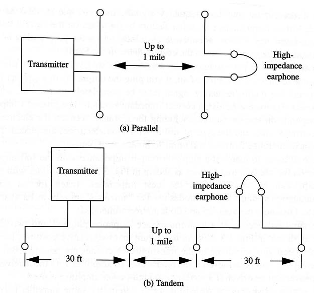
Note in this figure that two relative positions for the receiver electrodes as related to the transmitter electrodes are possible. But the best sensitivity can be achieved if the reader uses an amplifier with the receiver. A loudspeaker can be driven if a medium- to high-power amplifier is used.
For a bilateral system, as we will describe herein, the same ampliúer used to transmit the signals can be “inverted” to act as a receiver.
Recall that this is not a tuned system, as the audio signal is its own carrier, so the frequency range is spread between 16 and 16,000 Hz. As a result, if two or more transmitters are operating simultaneously in the same area, it will not be possible to separate the signals.
Also, atmospheric discharges (lightning), noise produced by industrial machinery, and many other noises will be superimposed on the signals, and it is not possible to avoid their influence. You can use audio filters to improve the system’s performance. You can increase the systemºs range if you just use an audio tone to send telegraphic messages in Morse code.
Summarizing, our project consists of an audio amplifier with additional circuits to transfer the signals to the ground and also to pick up signals from the ground at the receiving end.
Assembly
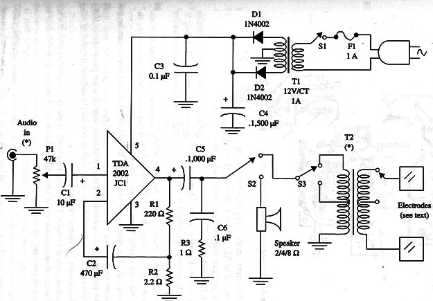
Figure 4 is a complete diagram of the “through the Earth” communication system.
The printed circuit board to the amplifier is shown in Fig. 5.
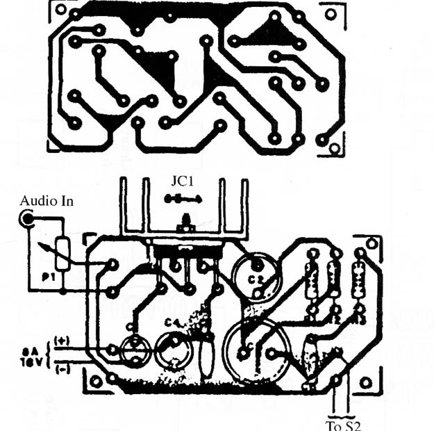
The TDA2002 is an audio amplifier integrated circuit. The output power is about 5 W, which is enough to communicate over distances up to 600 ft. The integrated circuit must be mounted on a heat sink.
For the input, we can connect any high-impedance microphone and adjust P1 to get the highest output power. The power supply uses a transformer with a primary winding rated to the ac power line and a secondary Winding that produces 12 V CT with current of 1 A or more.
T2 is any transformer with a low-impedance Winding with taps and a high-impedance winding with taps. You can experiment with a power transformer with a primary Winding rated to 117/220 Vac and a secondary Winding to 6 V to 12 V CT with currents in the range between 500 mA and 1 A. The low-voltage winding is connected to S3, and the high voltage Winding is connected to S4.
Using S3 and S4, you can find the best combination to obtain maximum energy transference to the Earth.
Any 4 to 8 ohm speaker rated for power of 10 W or more can be used. It is also possible to connect the output to a medium-impedance earphone when using the circuit as a receiver.
The electrodes used as antennas are metal bars or plates with dimensions shown in Fig. 6.
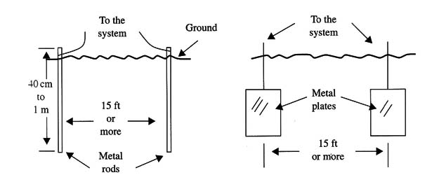
They should be placed deep in the ground. The reader can increase the soil conductivity, thereby lowering the impedance, by adding water and some salt. The wires used to connect the electrodes to the circuit can be as long as necessary.
If the reader doesn't intend to use an identical amplifier for the receiver (for Held operation), it is possible to use a high-impedance earphone (crystal or ceramic) connected as shown in Fig. 7.
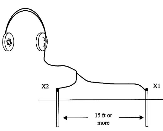
We must alert the reader that many earphones used in CD players and walkmans© are low-impedance types rather than the required high-impedance types, so they will not function with this circuit.
Another suggestion is to use a small, two-transistor audio amplifier that is powered from two AA cells as shown in Fig. 8.
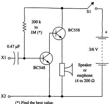
Other low-power amplifiers using such integrated circuits as the LM386, TBA820, TDA7052, etc. can be used in a portable receiver for this system.
Adjustments and Use
First, test the transmitter amplifier by speaking into the microphone with the loudspeaker connected to the output. Adjust Pl to achieve the highest output level without distortion.
Next, switch S2 to the transmit position, placing the receiver at a distance from the transmitter. Speak into the microphone and see if your voice can be heard in the receiver. Find the best combination of 83 and 84. You may also be able to prove performance if you use several electrodes that can be engaged by a switch.
Other Suggestions
The reader can conduct research on ways to improve this system. Some suggested experiments follow:
Try using an ultrasonic signal modulated by the audio signal and receiving it with a PLL filter.
Try using a phase modulated signal as used by modems.
Semiconductors
IC1 TDA2002 audio amplifier integrated circuit
D1, D1 1N4002 or equivalent silicon rectifier diodes
Resistors (1/8 W, 5%)
R1 220 ohm- red, red, brown
R1 2,2 ohm - red, red, gold
P1 47,000 ohm -potentiometer
Capacitors
C1 10 µF/ 16 WVDC electrolytic
C2 470 µF/ 12 WVDC electrolytic
C3 0.1 µF ceramic
C4 1,500 pF/25 WVDC electrolytic
C5 1,000 µF/25 WVDC electrolytic
C6 0.1 pF ceramic or metal film
Additional Parts and Materials
SPKR 4 to 8 ohm - 4 inch loudspeaker
S1 SPST toggle or slide switch
S2, S3, S4 DPDT toggle or slide switch 4
T1 transformer, 117 Vac primary Winding, 12 V CT secondary winding
T2 any high-impedance to low-impedance transformer (see text)
F1 1 A fuse and holder
X1, X2 electrodes (see text)
Printed circuit board, plastic box, power cord, knobs for the potentiometer, wires, microphone (see text), solder, etc..


