Features
Power supply: 6 to 9 Vdc
Frequency range: 530 to 1,600 kHz
Range: 6 to 15 ft
Small MW transmitters are easy to build but have some limitations in terms of
range, as low-power signals cannot carry over large distances.
Therefore, a small MW transmitter hasn’t the same range as an equivalent FM transmitter using the same components and generating the same output power.
This experimental MW transmitter can be used to send signals to a nearby receiver, and it has some interesting applications as suggested below:
As a wireless microphone, sending the signals to a nearby tape recorder or amplifier near it To transfer signals from one room to another, passing through the walls
To demonstrate ‘how a medium-wave station works for science fairs or in a school’s technology education program
The circuit is powered from four AA cells or a 9 V battery, and the sound comes from a high-impedance microphone or other source.
How the Circuit Works
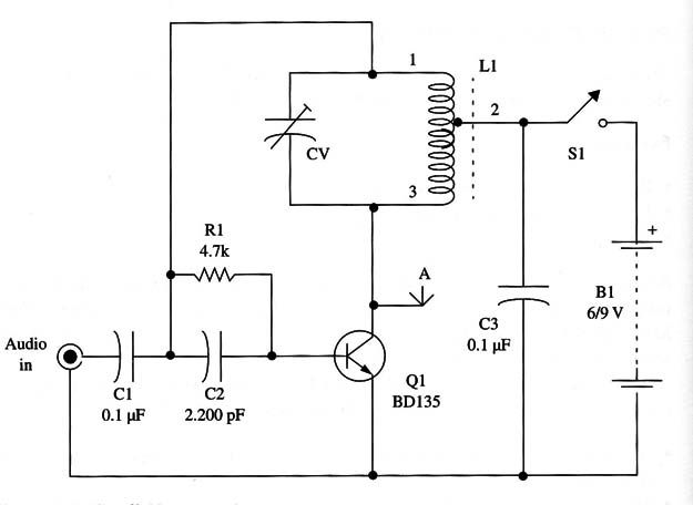
The circuit is a simple one-stage Hartley oscillator running in a range between 530 and 1,600 kHz. The frequency is determined by L1 and CV.
CV is a common MW variable capacitor, and it is used to find a free point in the MW band.
The feedback that keeps the circuit running is derived from tap 1 in the coil and capacitor C2.
Assembly
A schematic diagram of the circuit is shown in Fig.1.

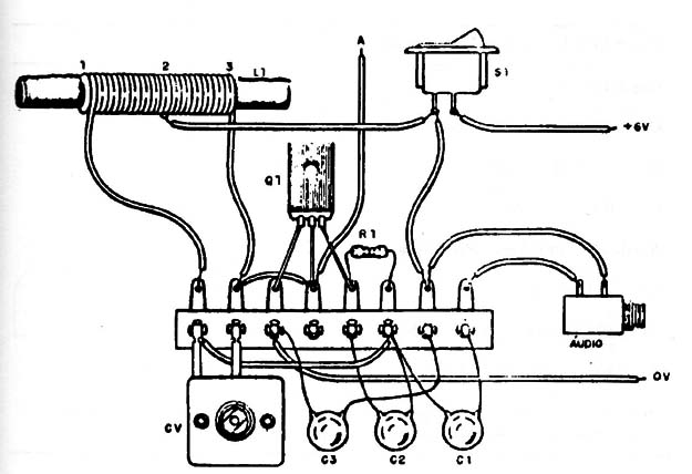
As the circuit is experimental and intended for beginners and students, the components can be mounted on a terminal strip as shown in Fig. 2.

The audio input connection is generally made by a jack and plug.
However, if the circuit is used as a wireless microphone, these components are not necessary, and the microphone can be connected directly to the circuit.
The capacitors are ceramic types.
Any variable capacitor with capacitances ranging between 120 and 360 pF can be used.
The antenna is a piece of rigid plastic-covered wire 10 to 40 in. long or a telescoping antenna.
The coil is formed by 40 + 40 turns of AWG 26 to 30 enameled wire over a ferrite core with diameter between 1/4 and 1/2 in. (0.8 to 1.5 cm) and from 4 to 10 in. (10 to 25 cm) in length.
The circuit can be installed in a small plastic box.
Adjustments and Use
Place any MW receiver near the transmitter and tune it to a free point in the band.
Power the transmitter up and adjust CV to find the signal. You must make this adjustment while speaking into the microphone.
When using the unit, keep the antenna in the vertical position, and don’t shake the device.
For an experimental broadcast station, the antenna can be a piece of common plastic covered wire 3 to 10 ft long.
A ground connection made at the negative pole of the power supply will increase the circuit range.
Semiconductors
Q1 - BD135 or equivalent medium-power NPN silicon transistor
Resistors (1/8 W, 5%)
R1 - 4,700 Ω -yellow, violet, red
Capacitors
C1- 0.1 µF ceramic or metal film
C2 - 2,200 pF ceramic
C3 - 0.1 µF ceramic
Additional Parts and Materials
L1 - coil (see text)
81 - SPST toggle or slide switch
B1 - 6 to 9 V, AA cells or battery
Printed circuit board, battery holder or clip, antenna, plastic box, input jack and
plug or microphone, knob for the variable capacitor, wires, etc.


