Note: the original project was published by the author in a Brazilian magazine. After, the articl was translated into English and inserted in a book published in USA.
Features
Power supply: 117 Vac
Plate voltage to the tube: 150 V (typical)
Output power: 2 W (typical)
Frequency range: 88 to 108 MHz
Range: more than 5 miles
Modulation: FM
High-power FM transmitters are special projects that are attractive to many readers.
Of course, the readers who intend to build one of them must observe all existing laws and regulations related to radio transmissions.
Although any high-power FM transmitters use transistors, the best and cheapest way to get a high power output in the FM band is via the use of a tube.
Using a 6C4 tube, you can build a 4 W transmitter that operates in the range between 88 and 108 MHz.
This means that the signal can carry up to several miles when the transmitter is used with an appropriate external antenna.
An important suggestion is to use the FM multiplexer stereo encoder described in this section.
This will allow the transmitter to perform as an experimental FM stereo radio station.
How to modulate the transmitter signal will be explained.
The transmitter is powered directly from the ac power line.
As the circuit is very sensitive to hum and noise, it is very important keep all the connections short, use shielded cables for audio and other signals, and use a metal box to contain the equipment.
Another important point to consider is that the circuit includes no isolation from the ac power line.
This means that shook hazards must be considered when the circuit is in operation.
All appropriate precautions must be observed to avoid such shock hazards when building and operating the transmitter.
The version described here is basic, and many improvements can be added by the reader to increase security and performance.
For example, you can I Add an isolation transformer to power the circuit, increasing physical security.
Include a varicap modulation stage to increase the audio fidelity.
Add filtering stages to the power supply to reduce noise and hum.
I Include a power supply that uses a high-voltage transformer to increase the tube plate voltage. This will increase the power output to more than 5 W.
How It Works
The circuit is based on a 6C4 triode tube.
This tube can be found in many old radio and TV sets (see thetube section I the site for more information about these devices).
Those apparatus use the 6C4 tube for several functions, i.e., as an audio preamplifier, detector, mixer, oscillator, etc.
Although the 6C4 is designed for audio circuits, it can oscillate at frequencies as high as 100 MHz.
The principal characteristics of the 6C4 tube are as follows.
Filament supply voltage 6.3 V
Filament current 150 mA
Plate voltage 300 V (max)
Grid voltage 50 V (max)
Plate current 25 mA (max)
Plate dissipation power 8 W (max)
Output power with a 300 V supply 5.5 W (max)
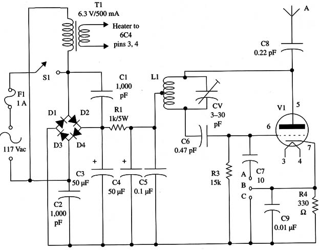
In this project, the 6C4 tube is wired as a high-frequency Hartley oscillator in which the frequency is determined by CV and L1.
Capacitor C6 provides the necessary feedback to keep the oscillations on, and R3 biases the grid.
Resistor R2 biases the cathode, keeping its voltage above the grid voltage - an important condition for correct operation.
One option is to channel the audio input signals to the cathode.
Applying the signal to this point, it is possible to alter the circuit frequency, thereby modulating the high-frequency signal.
Another input option, recommended for use when the transmitter is modulated from weak signals sources, is to the grid.
The power supply is formed by a full-wave rectifier using four diodes and a filter using three high-value capacitors.
The “pi” filter uses C3, C4, C5, and the resistor R1.
This filter is very important to reduce the hum that can be superimposed on the transmitted signal as modulation.
C5 must be a ceramic capacitor, as only this kind of component can be used to ground any high-frequency signal present at this point of the circuit.
To heat the filament, we use a small transformer with a secondary winding rated to 6 V X 250 mA or more.
Assembly Figure 1 shows the schematic diagram of the transmitter.
Although we are using a tube, it is possible to use a printed circuit board for the assembly, as shown in Fig. 2.
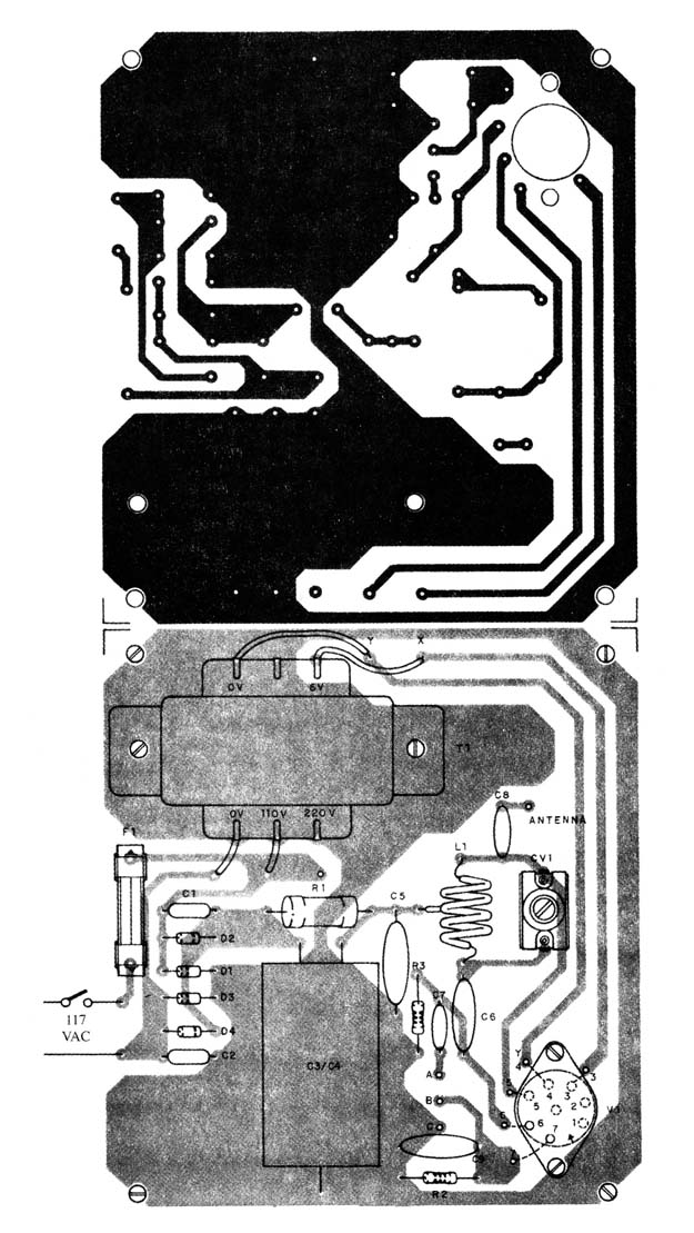
The tube’s pins can be soldered directly to the printed circuit board in the configuration shown.
The printed circuit board is fixed to a metal chassis.
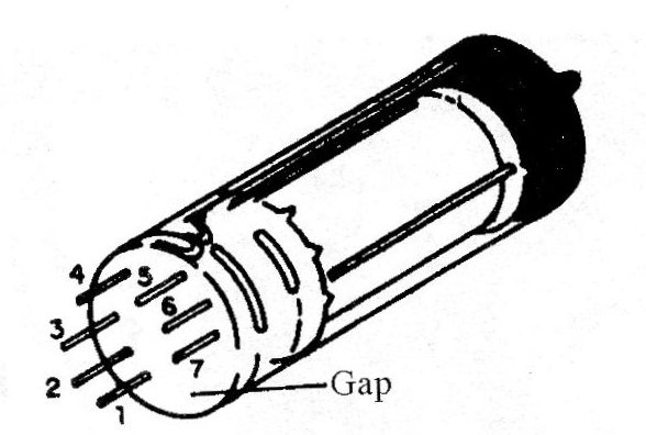
Observe that the tube’s pins are numbered starting from the large space and running counterclockwise as Fig.3 shows.
The connections from R1 and C1 to the oscillator coil must be as short as possible to avoid hum.
Filtering capacitors C3 and C4 are not critical, and units with capacitances between 16 and 50 µF can be used.
The voltage rating of these capacitors must be 200 V or more.
If you intend to power the circuit from a 220 V power line or use a high-voltage transformer, the capacitors’ voltage rating must be increased.
In many cases, it is possible to find dual capacitors for this task.
These capacitors are assembled in one case that can be fixed in a chassis as shown in Fig. 4.
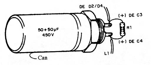
If this type of capacitor is used, mount it on the chassis with wires connecting it to the printed circuit board. Note that the negative terminal is the case.
The figure also shows how resistor R1 is wired.
The printed circuit board can be altered to receive this kind of component.
Another kind of electrolytic capacitor that can be used for this project is the one shown in Fig. 5.
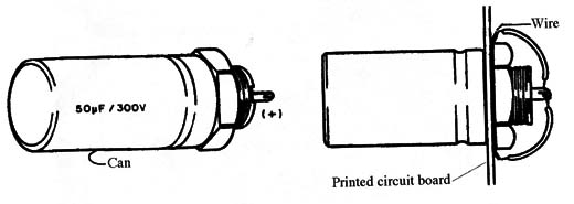
This type uses a nut to fix it to a chassis (over-chassis mounting). As the negative terminal is the case, when the nut is fixed in contact with the chassis, the negative connection is automatically provided.
R1 must be a 5 W resistor.
The coil is formed by five turns of AWG 18 to 24 enameled wire on a coreless form with a diameter of 1 cm.
Any porcelain or plastic trimmer with capacitances ranging between 2-20 and 4-40 pF can be used.
It is recommended that you use types that are designed for high-voltage signals, such as components that use mica as the dielectric.
Capacitors C6, C7, and C8 must be ceramic high-voltage types.
They must be rated to voltages of 400 V or more. 1l and C2 must be polyester or another metal film type rated to 400 V or more.
The transformer, used to heat the filament, has a primary winding rated to the ac power line voltage and a secondary rated to 6.3 V with currents of 250 mA or more.
If the reader uses a transformer with a low-voltage, high-current winding (6.3 V X 500 mA or more), it is possible to power a small incandescent lamp as well.
This lamp can be used to indicate when the transmitter is “on the air.”
The diodes are 1N4004 or 1N4007 if the circuit is powered from the 117 V power line.
If the circuit is powered from the 220 V or 240 V power line or from a high voltage transformer, the diodes must be the 1N4007 or equivalents.
The printed circuit board should be fixed on a metal chassis and installed in a box to avoid accidental touch, as all metallic parts are “alive” and can be dangerous shock hazards.
Adjustments and Use
Place the transmitter near an FM receiver tuned to a free point of the FM band (between 88 and 108 MHz) and turn on the power.
Use a piece of wire 5 to 10 inches long as an antenna when making these adjustments.
Wait two or three minutes for the tube to warm up.
This is normal, as the cathode does not begin to emit electronics until it is heated to a relatively high temperature.
In the same manner as a common incandescent lamp, the tube is heated by the electrical current.
The reader should consider this high temperature to be normal and avoid touching it when it is hot.
First adjust trimmer capacitor CV1 to tune the transmitter’s strongest signal to the receiver frequency.
You must take care not to tune harmonics or spurious signals which, because of the transmitters high power, will exist at several frequencies in the FM band.
The modulation comes from a small audio amplifier (50 mW to 1 W) wired as shown in Fig. 6.
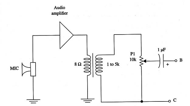
The trimmer potentiometer is adjusted to find the best modulation point in which the received signal is free from distortions.
Figure 7 shows a circuit that can be used to achieve the modulation using a varicap.
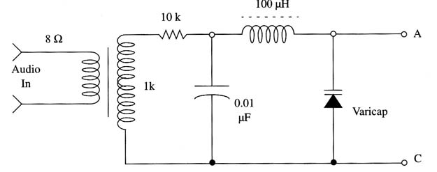
Any varicap can be used with this circuit.
The ideal audio signal amplitude for best modulation depends on the varicap’s characteristics.
After making all adjustments, the transmitter is ready to be used.
But, as always, take care not to violate federal regulations with this high-power unit.
Tube
6C4 miniature triode
Semiconductors (1/8 W, 5%)
D1-D4 1N4004 or 1N4007 (117 Vac power line) or 1N4007 (220 or 240 Vac power line)
Resistors (1/8 W, 5%)
R1 - 1,000 Ω x 5 W, Wire wound
R2 330 Ω - orange, orange, brown
R3 - 15,000 Ω-black, green, orange
Capacitors (400 WVDC or more except electrolytics)
C1, C2 - 1,000 µF, metal film
C3, C4 - 8 to 50 µF x 200 V (117 Vac) or 400 V (220 and 240 Vac) electrolytics (see text)
C5 - 0.1 pF ceramic*
C6 - 47 pF ceramic*
C7 - 10 pF ceramic*
C8 - 22 pF ceramic*
C9 - 0.01 µF ceramic*
CV trimmer (see text)
Additional Parts and Materials
F1 - 1 A fuse and holder
S1 - SPST toggle or slide switch
T1 - Transformer, 117 Vac primary Winding, 6 V x 250 mA secondary winding
L1 - coil (see text)
Printed circuit board, metallic chassis and box, input jack, antenna jack optional), power cord, etc.
(*) High-voltage types (400 V or more)


