Note: this article is part of my book Science Fair and Technology Education Projects.
This code uses dots and dashes to represent letters, numbers, and graphic signals. The dash is a long pulse, and the dot is a short pulse. A trained ear can receive the signals and decode them into letters, numbers, and graphic signals and reproduce an entire message.
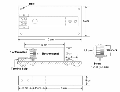
The receiver operates as follows: a flexible metallic blade beats against another piece of metal when the current flows across the circuit, and this an audible click.
When the current is cut off, the blade returns to its initial position and waits for the next pulse. The interval and duration of the clicks can be associated to dots and dashes.
Using a good receiver such as this one, the distance between the transmitter and the receiver can be extended up to 100 m (328 ft).
Figure 1 shows the receiver for the telegraph system.

LISTA DO AUTOR
Receiver
1 wood or plastic piece for the base, 10 x 5 cm (2 x 1 in.)
1 thin flexible metal blade measuring 10 x 1.5 cm (2 x 0.6 in.)
1 terminal strip with screws
1 1 x 1/8 in. screw for the electromagnet
1 washer and some nuts for the screw
20 to 50 m (65 to 165 ft) of enameled wire (30 to 34 AWG)
6 screws (for wood or with nuts) for parts placement
4 plastic or rubber feet
Other items: solder, wires, glue, etc.
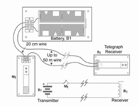
Figure 2 shows the complete circuit for the telegraphic communication system.

The manipulator can also be built using a base and metal blades, as suggested in the figure.
The Complete Circuit
B1-6 V (4 AA, C, or D cells with holder)
M1-Manipulator (telegraphic key)
R1-telegraphic receiver
40 cm of plastic-covered wire
10 to 50 m of plastic-covered two-conductor wire
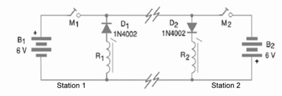
Figure 2 provides the schematics for a one-way communication system. The diagram for a two-way system is shown in Fig. 3.

When installing this circuit, it is very important to observe the position of the cells and the diode.
If the poles are changed, the circuit will not operate.
To construct the electromagnet, wind 200 to 2000 turns of enameled wire on the screw and leave a small gap (1 to 2 mm) between it and the upper blade.
Strip the enameled wire at the points where it connects to the circuit.
The circuit can operate with other voltages, in the range of 3 to 12 V, but the best performance must be achieved through experimentation. Maximum performance occurs when closing the circuit produces the highest attractive force in the magnet.
It is also important to avoid the condition in which both keys are closed, as this can cause a short in the system.
Competition
Organize a competition to determine who can transmit a complete message the fastest.


