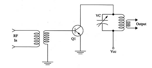
External power amplifiers used to increase the performance of a transmitter are called linear amplifiers and are very popular among radio amateurs. They can process signals in a range between 0.5 and 100 W, resulting in output signals in the range of 50 to 2,000 W.
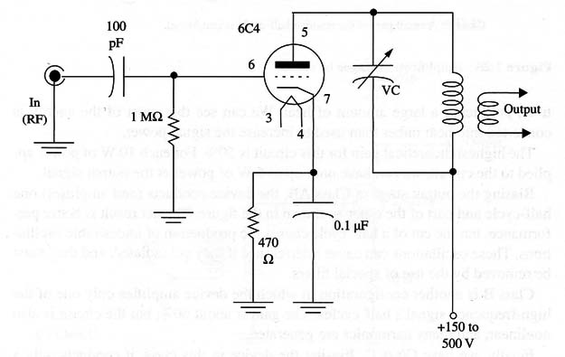
Figure 1 shows a diagram of a simple linear amplifier that can be used with small FM transmitters. The 6C4 tube is not an RF tube, and it can produce outputs up to only 4 W, but it is cheap and even can be found in old radio and television sets.
An important factor to be considered when projecting a power output stage is the class of operation.
We can see in Fig.2 that, depending on the bias of a stage, the signal can be cut at different amplitude points. The point is determined by the instant at which the device used in the stage becomes active or when the current flow begins.
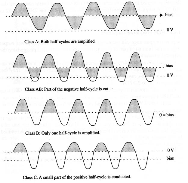
In Class A, the device (transistor or tube) is biased so that both signal half-cycles are amplified. This means that the current flows through the device all the time, producing a large amount of heat. We can see that most of the energy is converted into heat rather than used to increase the signal power.
The highest theoretical gain for this circuit is 50%. For each 10 W of power applied to the circuit we can have only up to 5 W of power at the output signal.
Biasing the output stage in Class AB, the device conducts (and amplifies) one half-cycle and part of the other as shown in the figure. The net result is better performance, but the cut of a half-cycle causes the production of undesirable oscillations. These oscillations can cause interference if they are radiated, and they must be removed by the use of special filters.
Class B is another configuration in which the device amplifies only one of the high-frequency signal’s half-cycles. The gain is about 60%, but the circuit is also nonlinear, and many harmonics are generated.
Finally, we have Class C. Biasing the device in this class, it conducts only a part of one half-cycle. The gain is very high, about 80%, as the input power is al- most all used to produce the output signal. It is also necessary to use a filter to eliminate undesirable signals produced by this configuration.
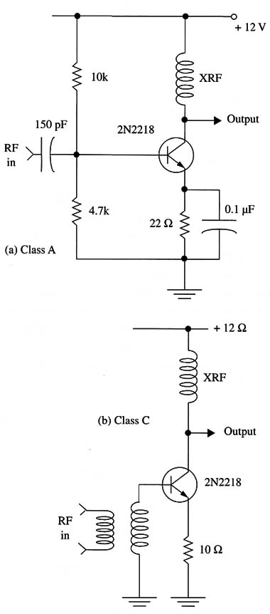
Some examples of circuits using the described configurations are shown in Fig. 3.
An important configuration based in the simple Class B biasing is the one called the push-pull stage. This configuration uses a two-transistor Class B bias as shown in Fig. 4.
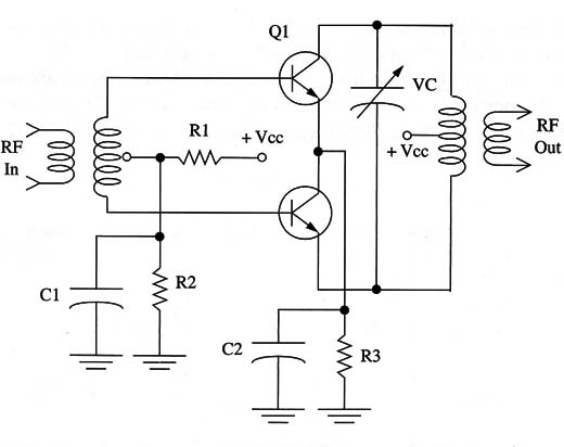
Each transistor amplifies one half-cycle of the high-frequency signal. This means that when one transistor is conducting, the other is cut off. The result is a high performance for the circuit, which converts nearly 100% of the applied power into the output signal.
Note that the amplifier stages can present two tuning configurations. One of them is the aperiodic configuration, so called when the circuit has no tuned circuits placed in the output as load. This circuit is very interesting, as it can operate in a wide range of frequencies without the need of adjustment.
Another configuration, shown in Fig. 5, uses a tuned LC circuit at the stage output. This circuit must be adjusted carefully to be resonant at the transmitter’s operation frequency.
