Note: this article was originally written in portuguese and translated to English by the author to be part of one of its books about the subject.
Thyristors are four-layer semiconductor devices intended for power control applications.
The family of thyristors is composed of devices that can be used in both ac and dc circuits.
The basic applications include both on-off control and the phase control where the amount of power applied to a load can be adjusted in a linear range of values.
In the following paragraphs, we will see how some thyristors work and how they can be used in robotics and mechatronics.
Silicon Controlled Rectifiers
The silicon controlled rectifier (SCR) is a four-layer device of the thyristor family.
The symbol, structure, and equivalent circuit are shown in Figure 1.
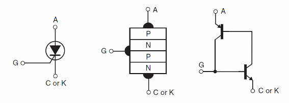
The SCR. as the symbol suggests, can be compared to a diode that conducts the current in only one direction once triggered.
To trigger on an SCR. it is necessary to apply a positive voltage to the gate.
This voltage biases the NPN transistor of the equivalent circuit to the saturated state. This causes a feedback that forces the PNP transistor into the saturated state as well.
Even when the trigger voltage disappears, the transistors remain on due to feedback. To turn off the SCR. there are two possibilities:
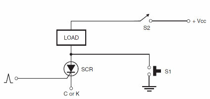
1. Create a short with a switch between the anode and the cathode, making the voltage between these elements fall to zero. Pressing the switch momentarily turns the SCRs off.
2. Turn off the power to the circuit. When the power is turned on again, the SCR remains off if no trigger voltage exists in the gate.
Figure 2 shows the basic application of an SCR in a control circuit. S1 and S2 are used to turn off the circuit.
Common SCRs are very sensitive and can be triggered by currents as low as a few hundred microamperes. Examples include the TIC106. MCR106, IR106, etc.
The trigger voltage for those devices is in the range of l to 2 V. The main current between anode and cathode is typically in the range of 100 mA to more than 100 A.
Using the SCR. SCRs can be used in both ac and dc circuits.
In dc circuits, we only must remember that the device remains on after the trigger signal is removed.
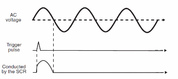
In the ac circuits, the SCR turns off when the voltage crosses the zero point at the end of each semicycle as shown by Figure 3.
After an SCR is turned on, we must keep a minimal amount of current passing across it to keep it on.
This current is called holding current and is in the range of a few milliamperes for common devices.
Another important point to be considered when using SCRs in low-voltage circuits is that a voltage drop of about 2 V is produced when it is on, as shown in Figure 4.
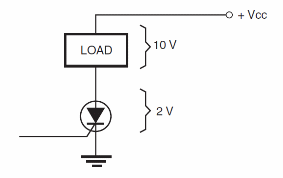
In some applications, this voltage drop must be compensated by an increase in the power supply voltage.
In high-voltage applications (plugged into the ac power line. for instance), this voltage drop can be ignored.
This voltage also determines the amount of power converted into heat by the device when in operation.
Triacs
The triac is another semiconductor of the thyristor family, also called alternistor, and it can be used to switch either ac or dc loads.
The difference between the SCR and the triac is that the triac can conduct current in both directions.
We can think of the triac as two SCRs wired in an anti-parallel mode with a common electrode for the gate.
Figure 5 shows the structure and symbol of a triac.

The triac is found primarily in ac circuits, since it is a bilateral device. In dc applications, the SCR is preferred.
Common triacs typically have trigger voltages in the range between 1 and 2 V and currents in the range between 10 and 50 mA.
The main current can rise from 1 or 2 A to more than 100 A.
Using the triac
Figure 6 shows the basic application circuit of a triac.
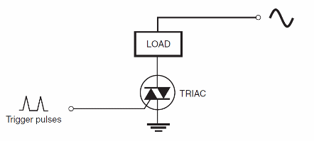
The load is Connected in series with main terminal 2 (MT2), and main terminal l is run to ground.
There are four ways to trigger the triac as shown in Figure 7.
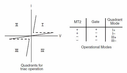
In basic applications, the trigger mode in the ñrst quadrant is the preferred one as it provides more sensitivity.
When tumed on a voltage drop of about 2 V occurs in the device. This voltage drop determines the amount of heat produced by the device (voltage drop x current = dissipation power).
Other Devices of the Thyristor Family
Many Other devices of the thyristor family can be used in projects involving power control. The following are the most important.
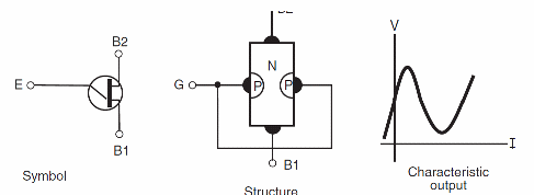
UJT - The unijunction transistor (UJT) is a device that presents a negative input resistance. This Characteristic makes it useful as an oscillator in low-frequency appliCations. Figure 8 shows the symbolg structure and characteristic output of this device.
The UJT can be used as a relaxation oscillator in the configuration illustrated by Figure 9.
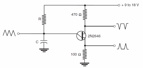
This circuit can be used to produce sawtooth waves or pulses in the frequency range between a fraction of a hertz and 100 kHz.
The most popular of the unijunction transistors is the 2N2646.
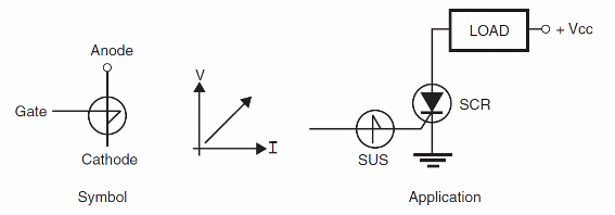
SUS - SUS is the acronym for silicon unilateral swtch. This device also shows a negative resistance characteristic that makes it useful as a trigger device for SCRs.
Figure 10 shows the symbol of this device and how it can be used in Circuits with SCRs.
Diac - The diac is a trigger device for triacs. This semiconductor device passes from the off state to the on state in a very short time when the voltage across it rises to a Certain Value (about 27 V for Common types).
As the diac triggers on with negative or positive voltages, it can be used to trigger triacs as shown in Figure 11.
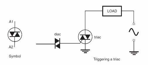
In some cases, the diac and the triac are mounted inside the same package.
The device formed by these two elements is also called a quadrac.
SBS - The silicon bilareml swirclz is another trigger device for circuits using a thyristor.
The symbol and appearance of this Component are shown in Figure 12.

The difference from this device and the diac is that the trigger voltage can be programmed by the control electrode.
Neon Lamp - The neon lamp is not really a solid state device. of course.
But this device, because of its negative resistance characteristic is useful in many circuits as a trigger element.
Figure 13 shows the symbol and appearance of a neon lamp.

The neon lamp passes from the off state to the on state, conducting current when the voltage across its terminals rises to about 80 V.
In many applications, the neon lamp can replace diacs and SBS triggering thyristors such as triacs and SCRs.
More about all these components the reader will find in the site.


