The basic FET is formed by a piece of N-type semiconductor material (silicon) where two P regions are formed (Figure 1).
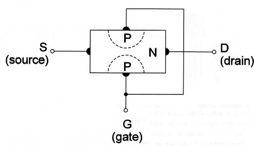
The current through the channel of P material, where the drain (d) and source (s) terminals are placed, can be controlled by a voltage applied to the gate (g) region.
The basic difference between a bipolar transistor and the FET is that, unlike the bipolar transistor that controls a collectoremitter current from a base current, the FET controls a current between drain and source from a gate voltage. The bipolar transistor is said to be a typical current amplifier and the FET is a typical voltage amplifier.
Like the basic material where the drain and source are placed (N and P), the FETs can be found in two types: N channel and P channel. This basic FET is referred to as JFET or Junction FET because, between the gate and the channel where the drain and the source are placed, exists a PN junction.
In the basic application the FET is wired as shown in Figure 2.
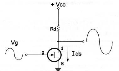
The voltage changes in the gate will be transformed into current changes between drain and source. if a signal is applied to the gate, this signal can be taken already amplified from the drain or source of the transistor according to the configurations.
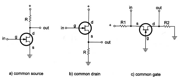
The FET can be used in the same configurations as the ones found in bipolar transistor circuits. The common drain, common source, and common gate configurations are shown in Figure 3.
Warning: FE Ts are very sensitive devices. The electric charge of your body can destroy the device if you touch its terminals.
Symbols and Types
Figure 4 shows the symbols used to represent both the P-channel and the N-channel JFET. The common types of these devices are shown in the same figure.

Observe that no external differences exist between a common bipolar transistor and an FET. The only way to know which one is which is by the part number or referring to the schematic diagram of the device.
Specifications
The electric specifications for an FET are important to help the reader find a replacement type or to know if it can be used in a project. The main specifications for an FET are:
A. Maximum voltage between drain and source (Vds)-the maximum voltage that can be applied to the FET, typically in a range between 20 and 60 volts. This specification can be abbreviated as Vds (max).
B. Maximum drain current-the maximum current that can be controlled by a FET. A common abbreviation in the databooks is Id.
C. Transconductance-the equivalent of the gain of bipolar transistors. It measures the inverse of the resistance between drain and source under certain conditions. The transconductance is measured in Siemens (S). In old publications, the antiquated unit mho (the word “ohm” inverted) is used.
D. Dissipation power-the same as in bipolar transistors and is specified in watts. Small FETs have dissipation powers in a range from 50 to 500 mW.
Where they are found
The JFET or FET is found in circuits where signals must be generated or amplified. Audio circuits and sensor circuits in alarms can use an FET in their input.
They can be used in the linear mode as amplifiers or switches like the common bipolar transistor. Figure 5 shows a typical stage where an FET is used as an amplifier for signals from a microphone or any other transducer.
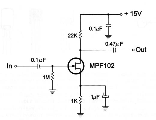
Stages like this can be found in commercial equipment such as alarms, radios, and remote controls.
When replacing an FET it is important to know the type and, if a replacement is used, the placement of the terminals as they can change from type to type.
Testing
The ideal for testing an FET is a special meter dedicated to this task.
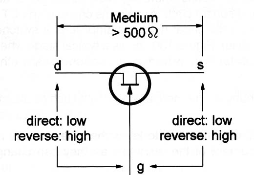
But, even using a simple multimeter, it is possible to detect if an FET has problems. Figure 6 shows how to test an FET measuring the resistance between its terminals.
