The integrated CMOS series can operate with voltages between 3 and 15 V, which also means greater design flexibility, since the sources may be suitable for the applications.
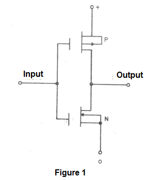
In Figure 1 we have an example of an inverter with P-channel transistor and N-channel of MOS type.
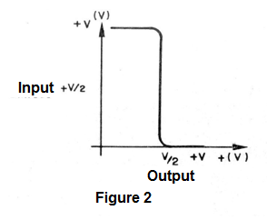
The transfer curve of this circuit is shown in Figure 2, where the values ??in which the transition from 0 to 1 occurs.
Another feature of the integrated CMOS is the extremely low input current that does not load the outputs.
The main series of the CMOS integrated is the one which starts with the 4000 (prefixes may appear according to the manufacturer as CD4000 by the RCA etc.).
An important factor must be observed dealing with the CMOS circuits.
Field-effect transistors have their inputs open in the logic circuits, which means that the extremely thin dielectric of the semiconductor is subjected to static discharges which can pierce it. If this happens the device is disabled.
Thus, handling the CMOS is delicate, we should avoid touching the pins directly on them, weld the component with the welder fed, or even leave the component on materials that can accumulate static charges such as plastic boxes/rugs, carpets etc..
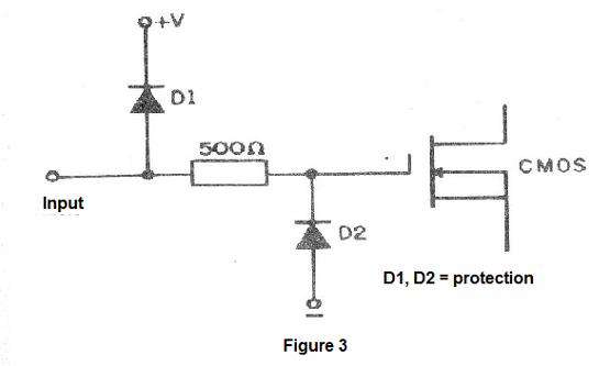
Depending on the manufacturer there is an internal protection for the integrated gate, consisting of a diode, as shown in Figure 3, but depending on the discharge intensity or its duration, the circuit may not be enough to prevent the component from being burnt.
Extreme care, since in the handling of the integrated CMOS:
- Avoid holding the terminals with your hands
- Use a socket
- Do not weld with a welding gun
- Always store them in a metal box or in the conductive sponge where they normally come from the manufacturer
Some rules of use are important:
- Do not let the input gates free: connect them to the ground or to the positive source, as the case may be.
- Always use high impedance probes when testing integrated CMOS.
Using Logic Circuits
Given families and types of functions, we can start with practicing. The first point to be observed is in relation to the enclosures where we obtain the integrated of the two families: CMOS and TTL.
Usually the ones we use most are the 14-pin DIL and the 16-pin DIL. DIL stands for Dual-in-Iine, ie, two rows of parallel terminals, as shown in Figure 4.
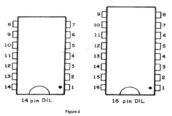
Note that for these enclosures there is a mark identifying pin 1, from which we count.
More complex functions may require larger number of pin enclosures, in some cases more than 40.
These integrated ones can be welded directly on a printed circuit board or fixed in a socket, as shown in Figure 5.
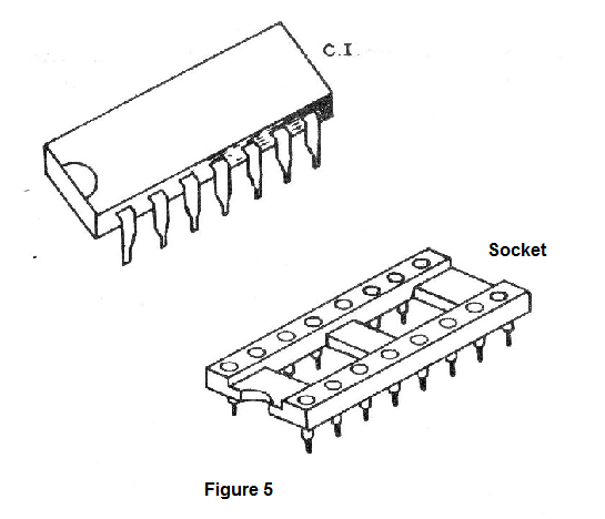
Low-cost "Molex" sockets are common and allow the use of an integrated from another experience. In fact, the use of the socket is always recommended, as it also prevents the thermal shock at the welding which may even damage the component.
For direct welding of the integrated, the welder must have a very thin tip and excessive welding must be avoided since it can spread and short circuit terminals (see Figure 6).
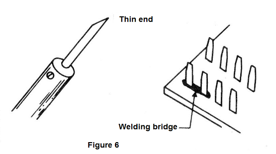
If this happens, the welding "bridge" can be eliminated with the help of the welder itself and a toothpick.
Heat the place and pass the toothpick to remove the excess welding and the problem will be eliminated.
To power your devices you will need a 5V source (if you work with TTL) or between 3 and 15V if you work with CMOS.
The experiments and assemblies that we will describe, will mostly be around the TTL integrated. Thus, the source we will build will be 5 V (which also works for CMOS, as they also work with this voltage).
There are built-in voltage regulators which make it easy to set up a source.
In particular we recommend the integrated of the series 78XX where the XX indicates the voltage which they provide at the output. Thus, using the 7805 we will have a 5 V output.
In Figure 7 we have the aspect of this integrated one which provides a current of 1 A and which needs to be endowed with a heat radiator.
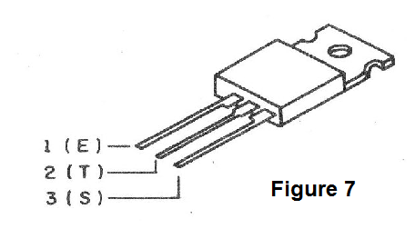
The input of this integrated can be between 10 V and 34 V, which allows us to use any transformer from 9 to 20 V approximately, with current of 1 A.
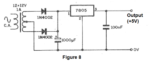
The finished circuit, shown in Figure 8, can be used to power projects with large amounts of TTL integrated.
For powering CMOS circuits we especially give a source with 7812 which supplies a voltage of 12 V (see Figure 9).
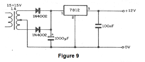
The integrated must also be equipped with a heat radiator, especially if a large quantity of components is supplied.


