
ART1513S ART159
MULTIPLEXERS
A multiplexer, or MUX for short, is a digital system that has several differential inputs where information appears in digital form, a data output, and control inputs, as shown in Figure 1.
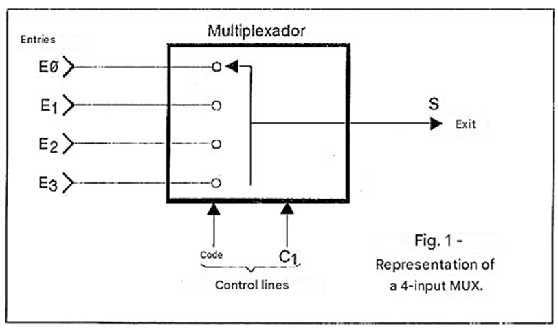
The signals applied to the control inputs determine which input will be connected to the output, thus transferring its signals. In other words, with a MUX it is possible to select which input will be connected to the output, simply through logical commands. A truth table can be associated with the multiplexer we gave as an example, where we have 4 inputs and one output:
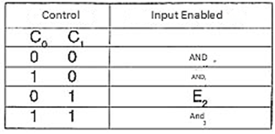
Therefore, when we want input E2 to be connected to the output, transferring its signals, all we have to do is bring control input C0 to a low level and input C1 to a high level. Note also that the number of control lines depends precisely on the number of inputs that must be selected. For a 4-input MUX, we need 2 control inputs, since with two digits we cover the 4 possible combinations of control states.
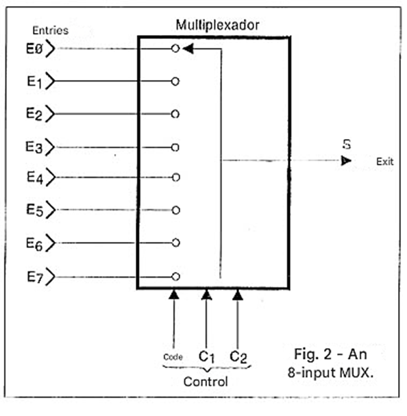
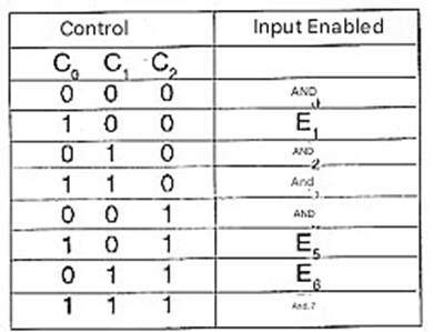
For an 8-input MUX, as shown in Figure 2, we need 3 control inputs, in order to obtain the 8 combinations of states that define which input will be activated.
A truth table for an 8-input MUX, as shown in Figure 2, would be as follows:
Implementing a multiplexer with logic gates can be done relatively easily. In the case of the 4-input, 1-output multiplexer we used as an initial example, we can use AND and OR gates in addition to inverters, as shown in Figure 3.
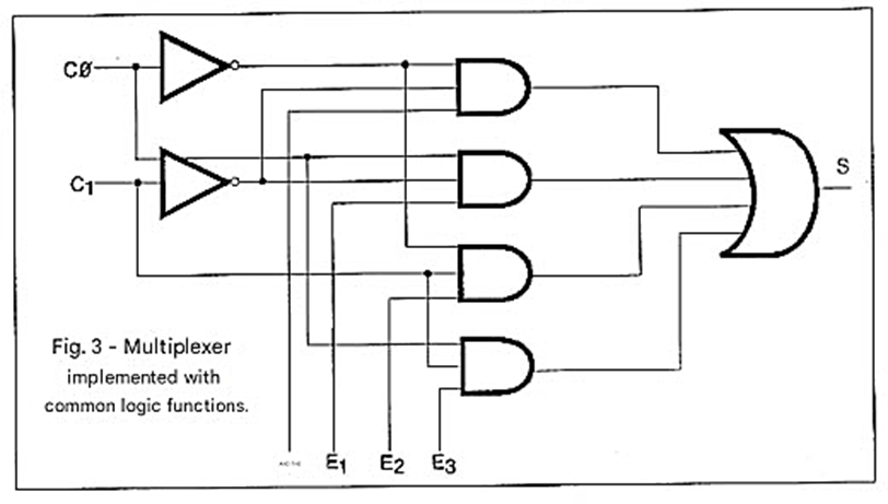
Multiplexer functions can be found in both CMOS and TTL integrated circuits, and these components also offer the possibility of finding an additional INHIBIT input that serves to deactivate the circuit, when necessary, thus disconnecting its output from any of the inputs. Note that this input can be important because in any combination of logic levels of the control input, we will always have an input connected to the output, and it may be necessary in some applications that no input is connected to the output at a given moment.
Figure 4 shows the logic circuit of an 8-input multiplexer with 3 control inputs and one INHIBIT input.
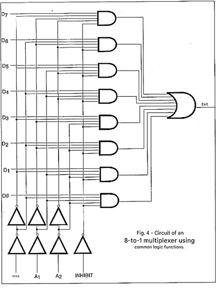
This circuit uses inverters, AND gates, and OR gates.
DEMULTIPLEXERS
A demultiplexer or DEMUX circuit has a data input and a certain number of outputs, in addition to control inputs, as shown in the simplified diagram in Figure 5.
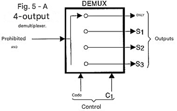
By applying appropriate logic levels to the control inputs, we can transfer the input signal to one of the outputs. Which output will receive the signal depends on the levels at the control input, as shown in the truth table below, for the example in Figure 5.
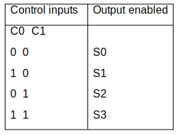
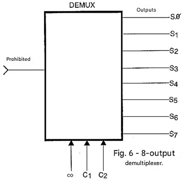
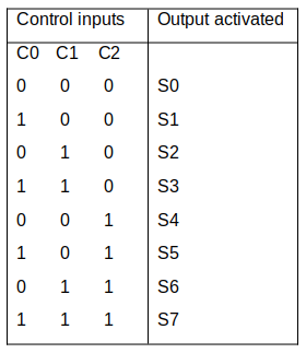
Note that, in this case as well, we need two control inputs to select one of 4 outputs. If we have 8 outputs, as in the DEMUX in Figure 6, 3 control inputs will be needed and the truth table will be as follows:
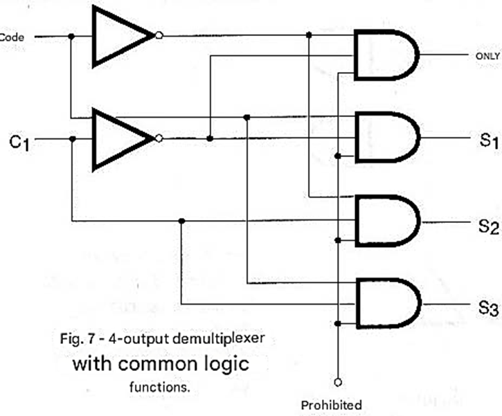
A demultiplexer circuit can be built from common logic functions. For a 4-output demultiplexer, such as the one used as the initial example in our article, it is possible to build it with only two inverters and 3 gates, 3-inputs AND , as shown in Figure 7.
Integrated Multiplexers/Demultiplexers
As we explained, the functions of digital multiplexers and demultiplexers can be found in the form of integrated circuits from both the CMOS and TTL families. Below are some common integrated circuits from these two families that can be used in projects.
74150 - 1 of 16 data selector
This is a 24-pin TTL multiplexer in a package, shown in Figure 8.
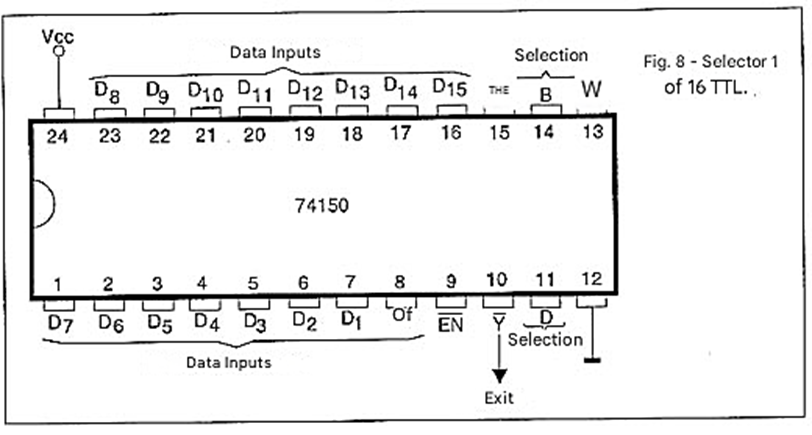
In normal operation, the EN enable input must be set to low. If the EN input is set to low, the circuit is inhibited and the output remains high regardless of what happens at any input or selection lines. This circuit also has an inverting characteristic: this means that the signal level of the selected input appears inverted at the output.
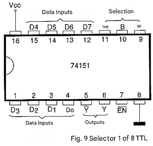
74151 - Data selector 1 of 8
This TTL circuit has 8 data inputs, three selection lines, and two outputs, one displaying the input signal in its original form and the other displaying it inverted. In normal operation, the EN enable input must be set to low. If this input is set to high, the Y output remains low and the Y/ output remains high regardless of what happens on the data or control lines. The 74151 is presented in a 16-pin DIL package with the terminal arrangement shown in Figure 9.
74152 - Dual Data Selector 1 of 4
This TTL integrated circuit contains two 4-input data multiplexers, with two control lines that act simultaneously on both circuits. Figure 10 shows the pinout of this component, which is presented in a 16-pin DIL package.
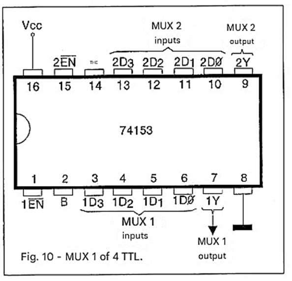
In normal operation, the EN input must be kept low. With this input high, the output of the corresponding multiplexer remains low regardless of the selected input.
74154 - 1 of 16 Demultiplexer
This TTL integrated circuit is presented in a 24-pin DIL package with the pinout shown in Figure 11.
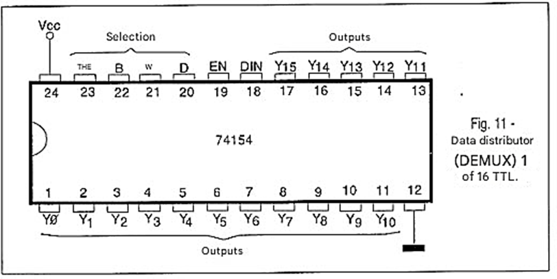
This type of circuit is also known as a data distributor, and in normal operation the EN input must be kept at a low level. With this input at a high level, all outputs will be at a high level, regardless of what happens at the data input and control inputs.
74155 - Dual Demultiplexer 1 of 4
This TTL integrated circuit is presented in a 16-pin DIL package, as shown in Figure 12.
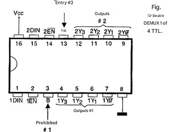
In normal operation, the EN input must be at a low level. With the EN input at a high level, all selector outputs are at a high level, regardless of the selection and input data.
4051 - Selector 1 of 8 (MUX/DEMUX)
This CMOS integrated circuit is presented in a 16-pin DIL package and can work with both analog and digital signals, depending only on the bias of pin 7, as shown in Figure 13 which shows its pinout.
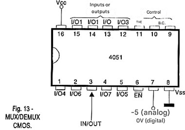
It is interesting to note that this circuit can function as both a multiplexer and a demultiplexer since the switches used are bilateral. When used in digital circuits, the supply voltage can be between 5 and 15 Volts, and pin 7 is grounded. If the circuit is used to operate with analog signals (audio, for example), the positive supply pin Vdd should be at 5 V and pin 7 at -5 V. The switched signals must have amplitudes that do not exceed this range.
With the EN input at a high level, all switches are open and no signal can pass. If EN is at a low level, the channel selected by the control inputs is connected to the output. The signal can flow from one of the input channels (X1, X2, X3, or X4) to the output (X) or vice versa, since the operation is both MUX and DEMUX, as we explained. The open switches for this circuit have a very high resistance of hundreds of megohms, and in the closed condition, they have a resistance approximately 120 ohms. The current in each switch cannot exceed 25 mA.
4052 - Dual 1 of 4 Selector (MUX/DEMUX)
This CMOS circuit works exactly like the 4051, with the difference that in this case we have two selectors (MUX/DEMUX) in the same integrated circuit in a 16-pin package, which is shown in Figure 14.
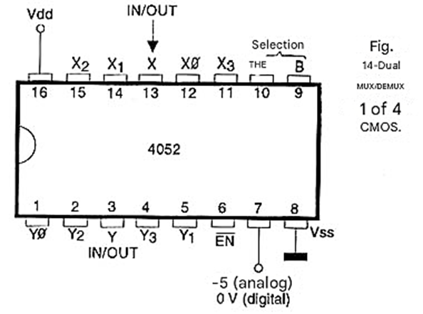
As in the previous case, the circuit can operate in both directions, that is, both as a multiplexer and a demultiplexer, and depending on the power supply, it can operate with analog or digital signals.
4053 - Triple Selector 1 of 3 (MUX/DEMUX)
Finally, we have a CMOS circuit that works like the previous ones, and that can be used as both a MUX and a DEMUX for both analog and digital signals.
The pinout of this integrated circuit is shown in Figure 15.
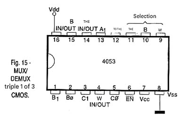
The output/input selection lines of the three selectors (MUX/DEMUX) in this integrated circuit are independent, but there is a common input for inhibiting operation. This input must be at a low level for normal operation.


