
ART1628S ART144
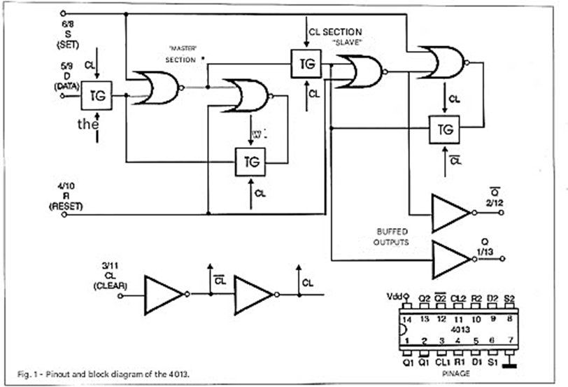
The 4013 integrated circuit is a dual D-type flip-flop with Preset and Clear. Figure 1 shows the pinout of this component, which is found in a 14-pin DIL (Dual in Line) package.
Its main characteristics are:
• Supply voltage: 3 to 18 V
• Maximum clock frequency: 10 MHz (10 V)4 MHz (5 V)
• Total current: 0.8 mA (1 MHz x 5 V) 1.6 mA (1 MHz x 10 V)
Each of the two flip-flops can be used independently in two operating modes: clock-triggered and direct-triggered.
COMPONENT DESCRIPTION
The 14-pin Dual In Line (DIL) package allows access to various points in the flip-flop circuit, highlighting the following functions:
a) CLOCK (CL) input through which we can control the circuit's state changes.
b) DATA (D) input where the reference level is applied, which is transferred to the output when the flip-flop's state changes.
c) SET (S) input that allows the establishment of a defined condition for the flip-flop.
d) RESET (R) input that allows the establishment of an initial output state of 0 for the flip-flop.
e) Complementary outputs Q and Q/, which are always at opposite logic levels.
f) VDD and GND (or VSS) power supply pins, which correspond to the +V pin and ground.
HOW THE 4013 WORKS
When the SET and RESET inputs are at a low logic level, the Q output acquires the logic state present at the DATA input at the exact moment the CLOCK signal is applied. Of course, the complementary output Q/ at that same instant will acquire the opposite logic level. The Q and Q/ outputs will maintain their registered level until a positive clock transition occurs, allowing the reading of the new state of the DATA input.
If the logic level applied to the DATA input remains the same, there will be no change of state of the flip-flop and the outputs (Q and Q/) remain in the same state. Note that negative transitions of the CLOCK input have no influence on the circuit, which maintains the levels of its outputs.
If the RESET input is brought to a high logic level and the SET input remains at a low level, the Q output will go low and the Q/ output will go high, regardless of the level of the CLOCK and DATA inputs. If we now set the SET input to a high level and keep the RESET input at a low level, the output Q goes to the high state and Q/ to the low state, regardless of the levels of the CLOCK and DATA inputs.
The conclusion we have is that the commands we make through the SET and RESET inputs have priority over the commands applied to the CLOCK input. And finally, if we set the SET and RESET inputs simultaneously to a high level, both outputs go to a high level, regardless of what happens at the CLOCK and DATA inputs. We can better describe this behavior using the following truth table:
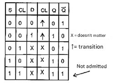
Figure 2 shows a timing diagram of the transitions in this integrated circuit, with the following definitions:
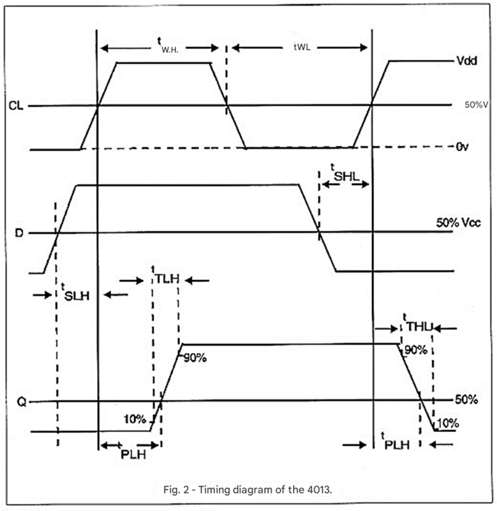
tWH - Minimum width of the clock pulse in logic state 1.
tWL - Minimum width of the clock pulse in logic state 0.
tSLH - Setup time for the positive output transition (0 to 1)
tSHL - Setup time for the negative output transition (1 to 0)
tpLH - Delay in the positive output transition
tpHL - Delay in the negative output transition
tTLH - Positive transition time or rise time
tTHL - Negative transition time or fall time
For 4013 integrated circuits with a 10 V power supply, typical values are:
tPHL(tip) = 75 ns
tTHL(tip) = 50 ns
tWH(tip) = 50 ns
tSHL(tip) = 10 ns
fmax = 10 MHz
APPLICATIONS
4013 integrated circuit can be used in two ways. Forms:
a) In CLOCK mode, the SET and RESET inputs must be grounded. The D input then determines what the flip-flop will do. The actual operation will only occur on the positive transition of the CLOCK input. If D is positive (high level), the CLOCK pulse causes Q to go high and Q/ to go low. If D is grounded, the CLOCK pulse causes Q to go low and Q/ to go high.
b) In direct mode, a positive SET (high) pulse forces the output to a high level and its complement to a low level. A positive RESET (high) input pulse forces the Q output to a low level and its complement to a high level.
CIRCUIT 1
Figure 3 shows a divide-by-2 circuit using one of the flip-flops from the 4013.
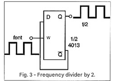
The complementary output (Q/) is connected to input D, to feed back into the circuit dividing the input signal frequency by 2.
CIRCUIT 2
The cascading connection of two flip-flops divides the input frequency by 4, as shown in Figure 4.
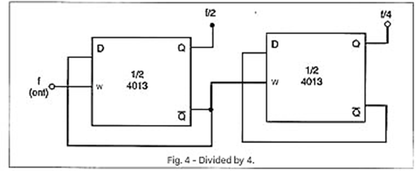
Note that the output for the second flip-flop is not taken from output Q, but from its complement.
CIRCUIT 3
With 3 flip-flops (which correspond to one and a half integrated circuits) we can make a divide-by-8 circuit, as shown in Figure 5.
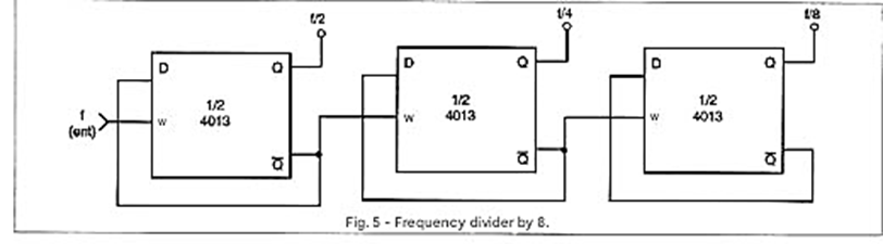
In the third flip-flop, every 8 input pulses will result in one output pulse.
Note that when using only one of the 4013 flip-flops, unused inputs must be grounded to avoid instability.
CIRCUIT 4
Activating a relay from pulses (from a monostable multivibrator, for example) can be useful in various types of control. Figure 6 shows a configuration that we frequently use in our projects due to its functionality and simplicity.
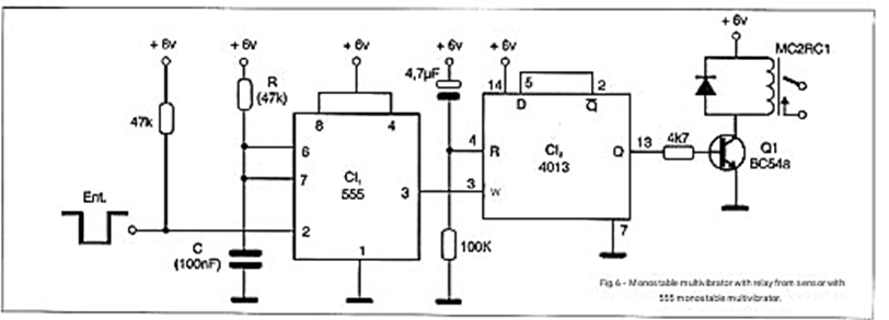
With each pulse produced by the 555 timer, obtained from an input sensor, the flip-flop changes state and, consequently, the relay also changes state. The duration of the output pulse of the monostable multivibrator (555) is calculated to avoid activating the sensor for more than an instant, producing multiple output pulses and thus causing erratic circuit operation.
CIRCUIT 5
Figure 7 shows a different application of the 4013, which can also be used as a monostable multivibrator.
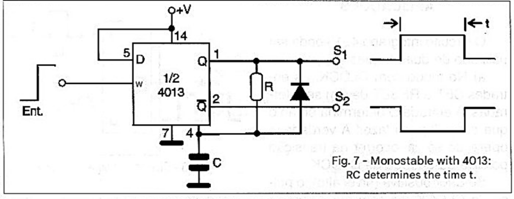
In common monostable multivibrators, there is internal feedback that determines the end of the produced pulse, at which point switching occurs. Connecting the output Q to a resistor that charges a capacitor C causes the RESET to be delayed, thus obtaining monostable behavior. Figure 8 shows a type of monostable using the 4013 where triggering occurs on the negative transitions of the input pulse.
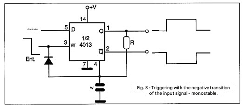
In both circuits, the diode serves to discharge the capacitor when switching occurs.
CIRCUIT 6
The possibility of using the 4013 in monostable configuration, combined with the input sensitivity of CMOS circuits, leads to very efficient touch switch circuits, such as the example shown in Figure 9.
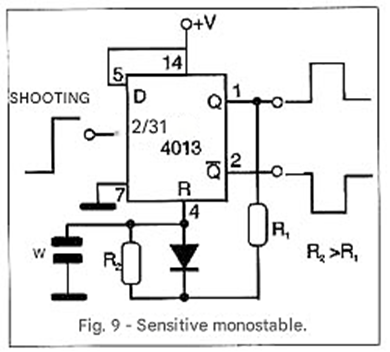
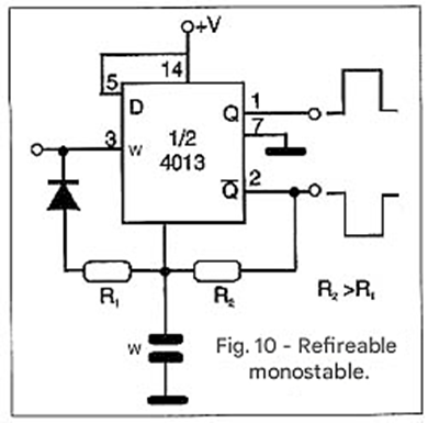
Figure 10 shows a circuit that can be retriggered, and in both cases, choosing an appropriate time constant is important to eliminate bounces.
Circuit 7
One of the application circuits we presented at the beginning of this sequence was a bistable switch where the 555 was used as a monostable to drive a 4013. Well, if we are only going to use one flip-flop to drive a relay, the other can perfectly well be used as a monostable, as shown in the configuration in Figure 11, which functions as an excellent touch switch.
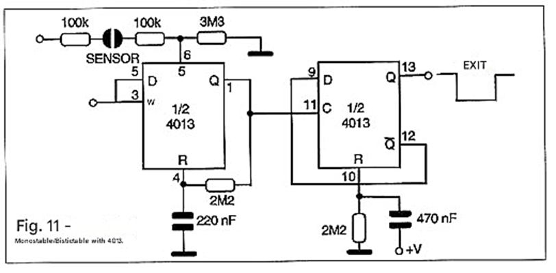
In this circuit, each touch of the sensor causes the relay to change state, thus switching an external load.
CIRCUIT 8
Figure 12 also shows a monostable proximity switch where the capacitance of our body (estimated at 200 pF) can be used to allow a signal to pass through, triggering the 4013 integrated circuit.
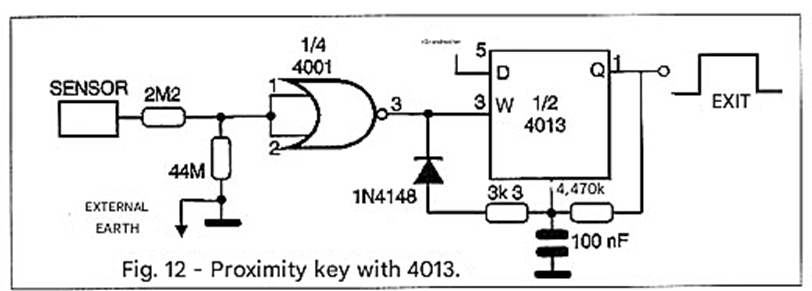
The 4001 (or 4011) is connected as an inverter and used as a trigger to provide a 60 Hz square wave signal to the 4013. The square wave signal comes from the power grid noise picked up by our body and transferred to the sensor when we approach it. A sensitivity control for this circuit can be implemented by placing a potentiometer connected to the sensor as a voltage divider. The 44 MΩ resistor can be obtained by connecting two 22 MΩ resistors in series or four 10 MΩ resistors.
CIRCUIT 9
We now present in Figure 13 the 4013 in its bistable configuration, where we use 3 flip-flops (1 and a half 4013s) as a "bucket brigade" or delay line sequencer.
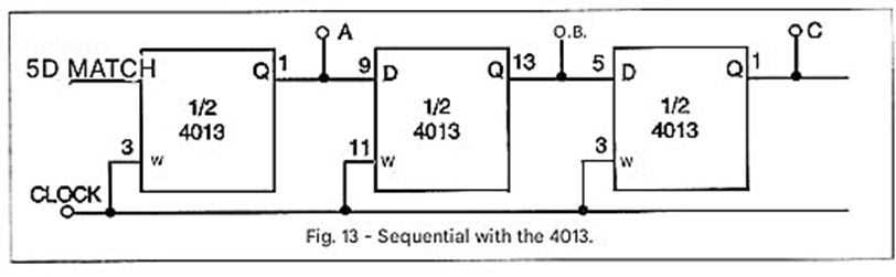
The behavior of this circuit becomes clearer by observing the output pulses as a function of the input pulses, as illustrated in Figure 14.
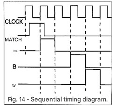
By directly activating a TRIAC or a SCR input, this configuration can lead to a very interesting 3-channel sequential effect. The speed of the flow or the effect will depend exclusively on the clock frequency. The 555 can be used in this type of project as an efficient clock.
CONCLUSION
The CMOS 4013 integrated circuit is more than just a pair of flip-flops, allowing the creation of hundreds of projects with the most varied configurations and operating modes. There are just a few, but the imaginative reader can easily create others, and perhaps even participate in our Special Edition, showcasing their inventive capabilities.


