Living beings are conductors of electric current. As such, they present variations of electrical resistance which can be associated to the most diverse phenomena.
It is precisely the research of these phenomena which offers an enormous field to both scholars and amateurs alike.
As an example of these phenomena associated with the variation of electrical resistance in living beings, the case of phonographs used in the detection of lies.
The variations in the skin resistance of the respondent accused by this apparatus are associated with imperceptible states of nervous tension which may indicate a lie.
Another important case is the variation of point-to-point resistance of a person's skin that can be associated with sensitive points and which can be selected for acupuncture treatments.
Finally, turning to the plant world we can indicate experiments with plants which have the resistance of their cells associated with states or behaviors of plants which cannot be visually perceived and which have been widely explored in the book "The Secret Life of Plants" other times mentioned in articles of this website.
Finally, for the amateur or the researcher, the availability of an apparatus capable of accusing very small variations in the resistance of a living being by means of currents which do not harm a person in any way constitutes an important laboratory resource.
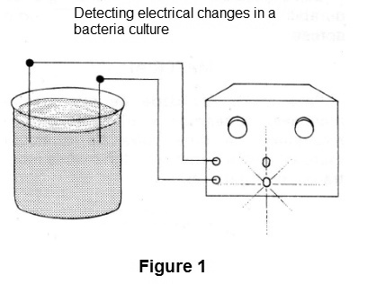
This apparatus, called the Bio Conductivity Meter, which we describe in this article, is capable of accusing small variations of resistance in living beings, is easy to build, uses few components and is also simple to operate (Figure 1).
The currents used in the resistance variation test are extremely low, on the order of millionths of an amp and do not cause any damage to the specimens being studied.
HOW IT WORKS
The basic bio conductivity meter is an integrated operational amplifier of the type 741. This amplifier is characterized by having a high input impedance of the order of 1 000 000 ohms and also by a high gain of the order of 100 000 times.
This means that extremely weak currents from varying the resistance of a living being can be amplified to the point that they can be used to trigger an indicator.
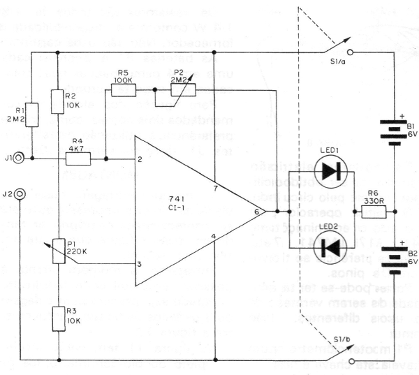
In Figure 2, we have the way the apparatus is connected for this purpose.
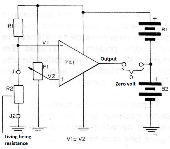
Between the J1 and J2 jacks are connected the electrodes which are coupled to the living being. The living being and the resistor R1 then form a voltage divider such that at its junction the voltage obtained will have a value which is proportional to the resistances, which is called the inverting input.
At the non-inverting input, we connect a second resistor network that has an adjustable element, the potentiometer P1.
When we adjust the potentiometer P1, so that the voltage at its central terminal (cursor) is the same as that applied at the other input, the amplifier "balances" and in these conditions, we do not obtain signal at its output (Figure 3).
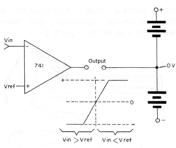
If now, there is a variation of the resistance of the living being, in the sense that it decreases, this causes a slight drop in the voltage at the inverting input.
As a result, it unbalances the amplifier, and as there is a "reversal" of the fall, we have an output rise in the output.
Likewise, if the resistance increases, causing a rise in tension, it will be accompanied by a drop in the output voltage, that is, it will tend to increase but in the negative direction. (Figure 4)
At the output of the amplifier we connect two LEDs in parallel and in opposition as detector elements. This connection causes us to have the following behavior for the circuit:
a) Both LED off - inputs in balance;
b) LED 1 on - resistance drop between the electrodes;
c) LED 2 on - increased resistance between the electrodes;
The gain of the operational amplifier is very high, which means that very small variations of the resistance between the electrodes can be accused.
In some cases, too great a sensitivity may hinder adjustment, or even be unwanted for the experience you have in mind.
We can control the gain of the operational amplifier with a negative feedback network as shown in Figure 5.
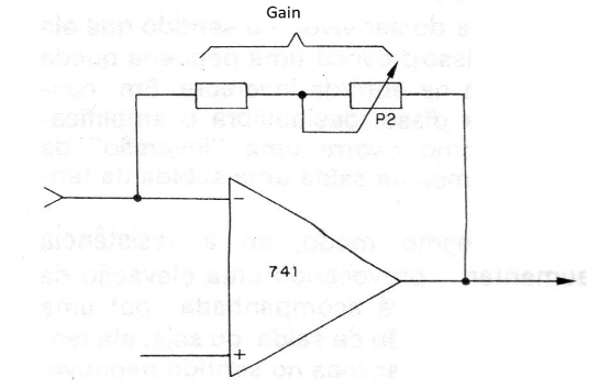
This network has a potentiometer where the gain control of the device is made.
Due to its characteristics, this device must be powered by a symmetrical source, i.e., two batteries must be used, each consisting of 4 small cells.
These batteries, however, will have great durability in view of the low consumption presented by the circuit.
MATERIAL
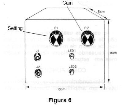
For ease of operation and handling, we suggest the use for a mounting box of any material of the shape and dimensions shown in Figure 6.
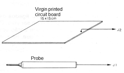
The electrodes can be of the most diverse types, depending on the purpose of the researches.
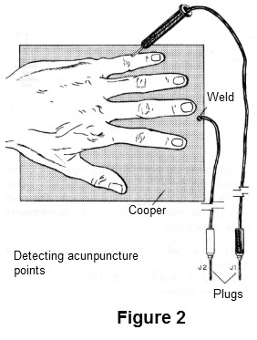
In Figure 7, we give a suggestion for electrodes used in the detection of acupuncture points.
At sensitive points we will have a detectable variation of resistance accentuated by the lighting of the LEDs (one or the other).
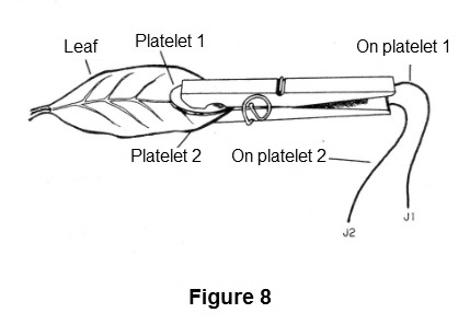
For plants, the electrodes may be two platelets of noble metal attached by a handle, as shown in Figure 8.
Electronic components are common and can be easily obtained. We start with the integrated circuit.
The operational amplifier can be found with such designations as 741, MC1741, LM741, uA741, etc. Preference should be given to the type with 8-pin DIL housing.
For LEDs, you can have both the possibility of both being red and using different colors. LEDs are common.
P1 is a single potentiometer with double key. This key is necessary, because by using a symmetrical source, the circuit must be turned off at two points. If it is difficult to obtain the dual-key potentiometer, use a single potentiometer and insert a separate double potentiometer.
P2 is linear 2M2 or Iog. The resistors are all 1/8 W or 1/4 W depending on the availability of your supplier. No capacitors are used.
Batteries B1 and B2 each consist of 4 small batteries which are placed in a suitable holder.
For the connection of the electrodes, two common terminals are recommended, with preference being given to the use of different colors. J1 should be red and J2 black.
ASSEMBLY
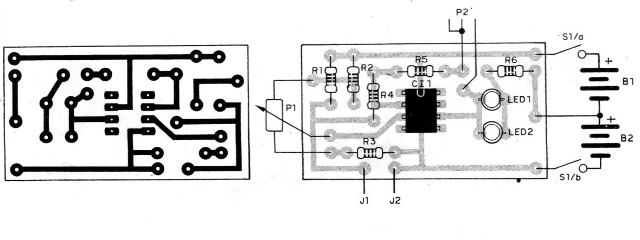
The best assembly makes use of a printed circuit board, which should be made by the reader, based on Figure 9 that shows it.
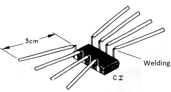
However, bridging is possible provided that the integrated one is carefully prepared by welding 8 pieces of rigid wire, as shown in Figure 10.
In Figure 11, we have the complete circuit of the bio conductivity meter where the components are represented by their symbols and have their values ??indicated.
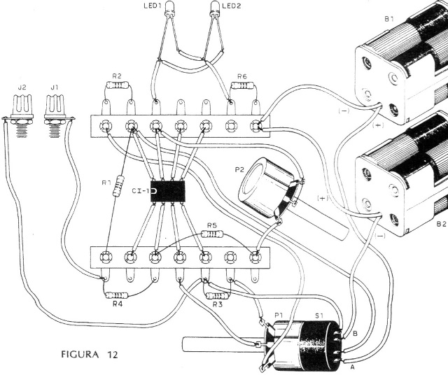
In Figure 12, shows the terminal strip assembly
The following precautions must be taken during assembly of this appliance.
a) First, weld the integrated circuit. Use support if you can, as this will not affect this component during assembly. In both cases, observe the position of the integrated one, depending on the mark that identifies the pin 1.
b) Then weld the two LEDs, observing that they are in an inverted position relative to one another, and that they must be placed on the board of the apparatus. Your connection will be made with pieces of flexible wire.
c) Weld the resistors. These components are not polarized, but we must observe their values ??that are given by the colored bands.
d) Connect the potentiometers and also their switches using pieces of wire with plastic cover.
e) When connecting the battery holders, observe their polarity. The red wires correspond to the positive poles and the black wires correspond to the negative poles.
f) For the connection of the J1 and J2 jacks use two pieces of flexible wire in the maximum length of 20 cm.
After the assembly has been completed, check all connections before making any tests of the device.
TEST AND USE
Place the batteries in the holders observing their polarity.
Then connect a 2M2 test resistor between jacks J1 and J2.
Set the potentiometer P2 to its maximum resistance position, i.e., higher gain.
Turning potentiometer P1 slowly at one time, one of the LEDs will turn off and immediately the other will light up. Going back a bit, carefully, you can get the exact point where the two LEDs are off.
This is the point of balance. Reducing the gain of the device by moving to the minimum position of P2, the reader will see that by rotating P1 we will no longer have a sudden transition from one LED to another.
After you finish testing the operation, you can use it.
To do this, connect the electrodes between jacks J1 and J2 and set P2 first for lowest gain. Then adjust P1 to the balance by increasing the gain while adjusting the balance until you reach the optimum operating point.
CI-1 - 741 - integrated circuit
LED1, LED2 - Common LEDs (one red and one green, or both red)
P1 - potentiometer 220 k with double key
P2 - 2M2 - single potentiometer
R1 - 2M2 x 1/8 W - resistor (red, red, green)
R2, R3 - 10k x 1/8 W- resistors (brown, black, orange)
R4- 4k7 x 1/8 W - resistor (yellow, violet, red)
R5 - 100k x 1/8 W - resistor (brown, black, yellow)
R6 - 330 R x 1/8 W - resistor (orange, orange, brown)
S1 - double switch (conjugated in P1)
B1, B2 - 6 V or 4 small batteries
JI, J2 - single terminals
Miscellaneous: printed circuit board or terminal bridges, mounting box, electrodes, holders for 4 batteries (2), buttons for potentiometers, etc.


