What we are describing is an ultra sensitive detector of magnetic disturbances which can accuse an electric discharge to distances of tens of kilometers and even a network energy outbreak of natural origin, artificial or unknown.
This is a very useful device for the field investigator, since it triggers an alarm when any magnetic disturbance (which may be associated with the appearance of a UFO) reaches its sensor.
The unit is powered by standard batteries and is very sensitive. The sensor can be achieved easily, which makes the assembly of the unit quite affordable and inexpensive.
In normal use, the detector must be left connected away from power transmission lines, or any equipment which may cause the alarm to trigger erratically, as shown in Figure 1.
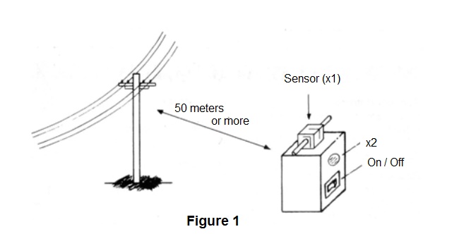
When capturing any magnetic disturbance, the device will emit an intermittent beeping sound, similar to a “beep-beep”, which works to alert the researcher that there may be something strange in the location and that some kind of phenomenon occurred nearby.
The close passing of a UFO is a possibility which should not be excluded.
As the power consumption of the device is very low, even being powered by batteries, it can be kept on for long periods, monitoring events in suspicious locations.
Higher consumption only occurs during ringing, but, even then, an uninterrupted set of batteries should last for several days.
Another important feature of the detector is that it has no adjustments, which greatly facilitates its use.
How it works
We begin by showing the readers the complete detector diagram in Figure 2.
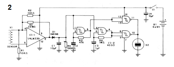
The sensor consists of a coil which must have as many turns as possible to obtain great sensitivity. Our suggestion is to take advantage of an unused transformer coil, which can have more than 10000 turns in the primary winding, which provides excellent sensitivity.
To further increase this sensitivity we will place inside this coil a ferrite rod, as shown in Figure 3.
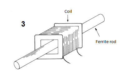
The purpose of this ferrite rod is to concentrate the lines of force of a magnetic field which must be detected.
When a variable magnetic field cuts the coil turns, a voltage is induced, being amplified by an operational amplifier of type LM339. This amplifier has a very high gain, increasing the induced voltage thousands of times, to the point of switching.
With this switching, which takes its output to have a positive voltage for an instant, the diode D1 leads and with that the capacitor C1 charges.
The capacitor load causes the two oscillators formed by the NAND ports of a 4093 integrated circuit to trigger.
The first oscillator generates an audio pitch determined in frequency by components R5 and C2, while the second oscillator generates flashing pulses determined by C3 and R6. Readers can change these components to obtain the pitch and flashing of the alarm signal as desired.
Pitch and flashing are combined on the other two ports of the integrated circuit in order to obtain a signal which can be reproduced by a transducer. This signal, consisting of “beep-beeps”, is reproduced in the ceramic transducer X2.
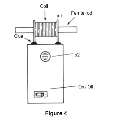
In Figure 4, we give an idea of ??how the device will be ready.
Assembly
The arrangement of the components on a printed circuit board for this assembly is given in Figure 5.
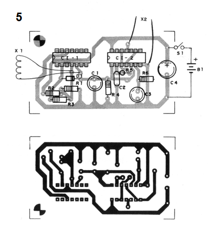
It is convenient to assemble the integrated circuits in sockets, especially if the reader is not very experienced in the treatment of these components.
The resistors are 1/8 W and the electrolytic capacitors must have working voltages of at least 6V if this is the voltage used in the power supply. If a 9 V battery is used, the working voltage of the capacitors must be at least of 12 V.
The other capacitors are ceramic or polyester and the diode is of general use, admitting equivalents.
The transducer X2 may be any of the high impedance ceramic type, including a microphone capsule. Note that low-impedance transducers cannot be used in this application.
The sensing coil X1 can be harnessed from a power transformer with primary winding of 110 V or 220 V and any secondary from 5 to 12 volts with currents from 50 mA to 500 mA.
By removing this transformer, as shown in Figure 6, we can remove the spool, and then fix the ferrite rod inside the spool (use glue for this purpose).
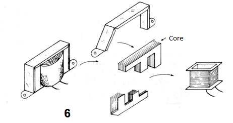
The winding terminals to be used are the high voltage ones which correspond to the plastic cover wires and not to the enameled wires.
This coil should preferably be secured so that the rod tips are out of the box, better capturing the magnetic fields.
Note that it is important not to use magnetic transducers as a speaker in this type of circuit, because given its sensitivity it can cause feedback causing erratic triggering.
Test and Use
To test the device, simply turn on its power. If the trigger is erratic and it does not stop, move it away from any connected electronic equipment or power supply lines. If the triggering still persists, take it away from home. If the device stops, then an excess of sensitivity will be characterized which can be reduced by the reduction of the value of R3.
To test the operation, if it does not trigger under the indicated conditions, take a small magnet and move it quickly in the vicinity of the sensor coil. There must be the ringing of the alarm.
Approaching the detector of electronic devices that operate with intense magnetic fields, such as televisions, motors and others, it must trigger. In some cases, even the simple approach of the wiring harness of an electrical installation can cause the triggering.
Take all of this into account when using the appliance. It must be away from devices which may cause a false alarm, such as power lines, electronic devices, magnets which may be inadvertently moved, etc.
The reader will also realize that a strong atmospheric discharge can cause the device to trigger, especially in the most sensitive condition.
If the reader wishes to add a sensitivity control, it can replace the resistor R3 with a potentiometer of 10 M ohms in series with a resistor of 1 M ohms.
To change the duration of the alarm pitch, simply change the value of C1, which can have values between 1 uF and 100 uF.
To use, look for the position of the coil (vertical or horizontal) which results in the best sensitivity, without however triggering with sources of magnetic interference that are identified.
The appliance can be kept switched on for long intervals.
Semiconductors
CI-1 - LM339 or equivalent - quadruple voltage comparator
CI-2 - 40938 - C-MOS integrated circuit
D1 - 1N4148 - silicon diode
Resistors (1/8 W, 5%)
R1 and R2 - 10 k ohms - (brown, black, orange)
R3 - 22 M ohms or 20 M ohms - (red, red, blue)
R4 - 100 k ohms - (brown, black, yellow)
R5 - 47 k ohms - (yellow, violet, orange)
R6 - 1 M ohms - (brown, black, green)
Capacitors
C1 - 10 uF / 6 V - electrolytic
C2-47 nF - ceramic or polyester
C3 - 1 uF / 6 V - electrolytic
C4 - 10 uF / 6V – electrolytic
Miscellaneous
X1 - sensing coil - see text
X2 - ceramic transducer - see text
S1 - single switch
B1 - 6 V - 4 small batteries (or 9 V battery)
Printed circuit board, transformer to remove sensor coil, etc.


