What kind of energy emanates from people endowed with "paranormal" powers when in concentration or when they manifest their strange abilities?
What kind of energy causes the snow to melt around the Tibetan monks in concentration in the middle of the night, or who moves objects on a table or deforms them without having to be touched?
What form of energy seems to emanate from the "nice" or "friendly" people that makes them so attractive?
No one knows if there is indeed a form of energy allied to these phenomena, but the "exologous" literature explores it a lot.
The ancient Hindus call this energy Prana; the old alchemists cite it as a "vital fluid" while modern Soviet researchers call it "bioplasma."
One of the most common modern denominations for this form of energy is "psychokinetic", or abbreviated PK. How to detect PK energy is what we will see in this article.
As a rule, it seems that all people are sources of this strange energy, which can be concentrated, directed or diluted according to our will, but after a certain training.
This "training" is what monks, gurus and other "mystics" do in order to direct their efforts to master this energy.
Detecting this form of energy is a problem that electronics can solve, although in principle we do not know exactly what this energy is.
But there is a fact associated with this energy which can contribute to its detection: in states of concentration, meditation, relaxation, this energy is manifested according to variations in the temperature of our body.
As we mentioned at first, it is observed the Tibetan monks master their body in the sense of producing this energy, which they can leave at dawn in the low temperatures of the heights of those mountains and putting themselves in a cold place they manage to melt the snow around them, apparently effortlessly, with their "mental powers."
If we cannot detect this psychokinetic energy directly, we can with the help of electronic resources detect the temperature variations which it provokes under certain conditions when it manifests itself.
This is our psychotronic detector: an ultra-fast and sensitive detector of temperature variations, especially from fingertips (where it seems that this energy focuses on emanation, since they seem to act as "antennas"), to be used in experiments of concentration, meditation or other exologous phenomena.
Very simple to assemble, it will not offer difficulties to the researcher, even if their specialty is not electronics.
HOW IT WORKS
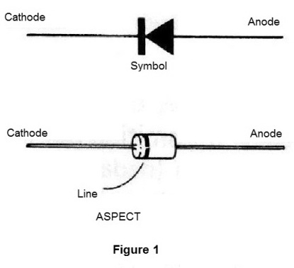
The "heart" of our psychotronic detector is a silicon semiconductor diode.
This component, whose appearance and symbol are shown in Figure 1, behaves like a sensitive electronic "thermometer".
In fact, when we polarize it in the opposite direction, that is, by connecting a battery so that it is "in reverse" of what would be required for the normal conduction of the current, we find that even a small current of the order of one millionths of an amp circulates by the diode. (Figure 2)
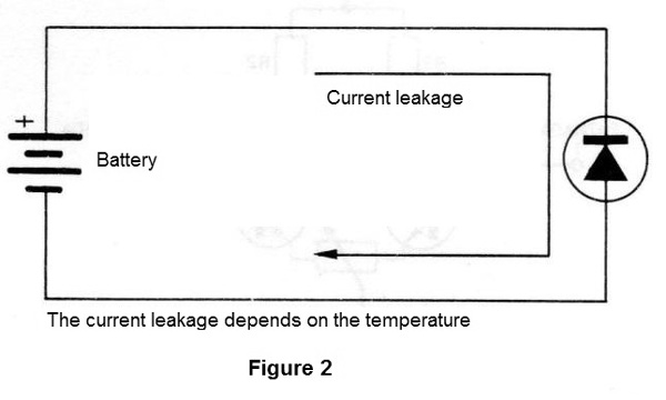
This "leakage" current is caused by the shaking of the atoms of the semiconductor material from which the component is formed, which release "from time to time" carrying electrical charges.
It is important to us this leakage current depends fundamentally on the temperature of the diode, which may be very small, ie having a small thermal capacity, easily accompanies variations in the environment temperature and even feels the temperature variations of bodies placed in nearby.
Thus, if we approach the diode of our mouth and let out a "puff" of hot air, this will be enough to provoke a sensible change of its temperature and also of its electrical conduction.
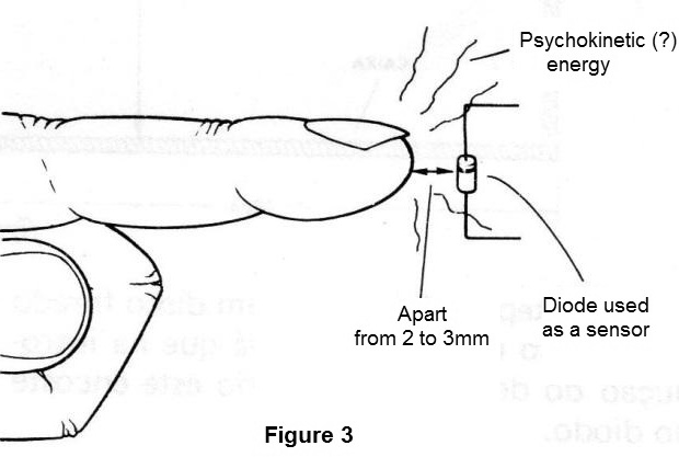
Likewise, if we approach the diode of our fingers, the temperature variations between the finger itself and the "environment" caused by the emission of psychokinetic energy may cause a sensitive change in its electrical conductivity (Figure 3)
Acknowledging the variations of this current which circulates in the diode, and is very weak, we need a special circuit.
The circuit used is a differential amplifier with 4 transistors as shown in Figure 4.
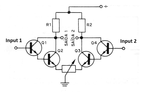
In this circuit, we have two "Darlington" pairs, that is, the transistors are connected in pairs in order to multiply their sensitivity.
This means that a very small variation of diode conductivity by temperature is already translated into a very large variation of current in the transistors.
At each input of the amplifier, a diode is connected, so that the circuit operates with two sensors, and in the output we have a single meter which is an instrument that allows to "translate" the current variations of the transistors.
The operation with two sensors, that is, two diodes, allows the realization of interesting experiments.
In fact, when we use a diode, the variations in behavior in increasing the temperature increase the current of the meter, that is, the needle moves to the right.
On the other hand, the same variations in the other diode decrease the current and the needle moves to the left.
If temperatures in both diodes rise at the same rate, the current in the meter stays, and nothing is indicated: the needle remains still.
The device is powered by a 9 V battery, which will have a very long life, since the consumption of the psychotronic detector is very low.
The operating settings are few: only the operating point of the sensor, ie the middle of the scale, in three potentiometers.
THE COMPONENTS
All components used in this assembly can be easily obtained.
The box must be special in order to allow the experiment to be performed.
Thus, in a wooden box with the dimensions shown in Figure 5, two tubes made of PVC pipes are inserted into which the sensor diodes will be placed.
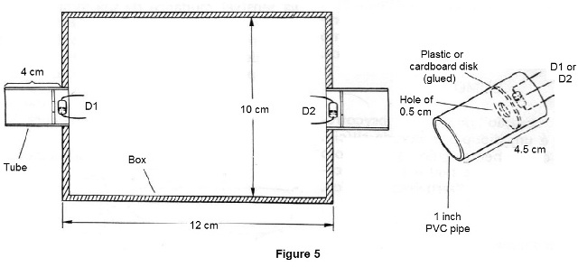
A bulkhead made with a plastic or PVC drilled disc will prevent the introduction of the finger from the researched one on the diode. This is necessary because the device must operate with the heat transmitted by irradiation and not by contact (nothing prevents the reader in a second version from working with the diodes in contact with the patient's skin, which can also lead to an interesting series of results).
Electronic components are all common. If the reader opts for the printed circuit board version, you must have the resources for its elaboration, otherwise it should be done on a terminal bridge.
The only terminal bridge used as a chassis can be easily attached to the inside of the housing.
We start with the diodes used as sensors. We can say that virtually any silicon diode of general use, such as 1N914, 1N4148, BA315, can work.
However, of all that we have tried, the type which presented the best sensitivity was BA315, which we recommend in particular.
The transistors are of the BC548 or BC238 type. Good quality non-leaking types should be chosen. This leak can be verified with the multimeter in the highest range of resistors, as shown in Figure 6.
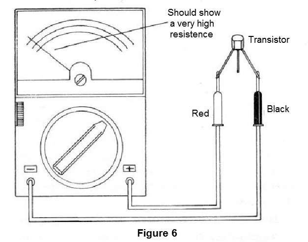
The pointer should indicate a very high resistance, that is, it should practically remain stationary.
If the transistor is leaking, it will cause serious adjustment problems for the detector, which may not work at all.
The indicator instrument is a common low-cost VU that has a coil for 200 uA. This instrument is easily found in electronic houses.
The potentiometers have all common values. The 10M, which may be harder to find, may be replaced by a 4M7.
Resistors and capacitors are common, as is the main switch S1 and the battery connector.
ASSEMBLY
For the welding of the components in the electronic part of the assembly, a low-power welder of good quality must be used. The welder should have a thin point and as additional tools, those which allow to hold, cut or adjust components.
In Figure 7, we have the diagram of the psychotronic detector with the components represented by their symbols and their values.
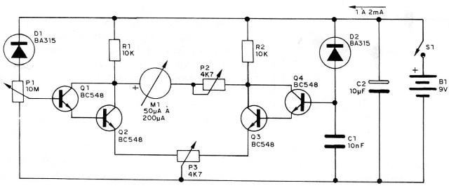
In Figure 8, we have the bridge version of terminals that is recommended for those with less technical resources.
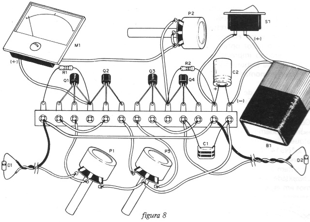
The welded terminal bar used as a chassis can be purchased in chunks at specialized houses and cut as indicated.
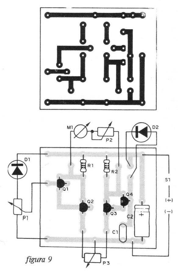
In Figure 9, we have the printed circuit board for this version.
When carrying out the installation, the reader must take special care and it is recommended to follow the following sequence:
a) Weld first the 4 transistors (Q1 to O4) observing their position. Note that two of them have the flat part facing down, while the other two have the flat part facing up. Be quick in welding the transistors as they are sensitive to heat. In the board version the position must also be observed.
b) Weld resistors R1 and R2. These components have the same value given by the colored lines in their casing.
c) Weld the capacitors C1 and C2. See that C2 is polarized, that is, the position of its positive pole must be followed according to the board or bridge designs.
d) Make the interconnections between the indicated points of the terminal bridge (3 wires) using common pieces of wire.
e) First, connect the potentiometer P3 using pieces of 10 to 15 cm of flexible wire. Later, this component will be fixed to the cover of the box, like the others.
f) Connect the instrument (which should be placed on the panel) and P2 (which should be on the cover) using flexible wire pieces as well.
g) Connect the potentiometer P1 using also pieces of flexible wire to allow their attachment to the housing cover.
h) Make the connection of S1 and B1. Note that the polarity of B1 must be observed. B1 will then be attached to the box with the aid of a clamp and S1 placed on the cover.
Complete the assembly with the diode connection. Note that wires of different colors are used, as you will need to observe the polarity of these components given by the rings in their casing. If there is reversing, the unit will not work. Attach the diodes to the tubes at the position indicated, near the hole in the separator disc. The attachment can be done in several ways, such as with the aid of a piece of foam or cork placed on the inner side of the tube so as to pass only the wires.
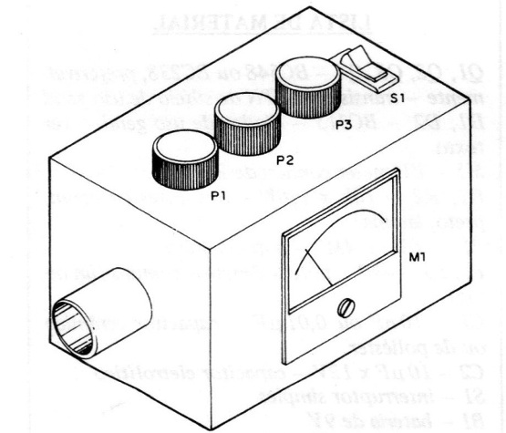
In Figure 10, we have the appearance of the device as it should be after it is assembled.
Before closing it permanently in its box, the reader should check its operation.
TEST AND USE
It will not be necessary to call any Tibetan monk or equivalent for a function check.
After checking all connections, connect a new 9 V battery.
Turning on S1, the instrument M1 may already mark something, ie the needle will move.
Then, adjust the controls as follows: initially, set P1 to the minimum resistance position, i.e. all the way to the right.
Set P3 to its center position and set P1 so that the instrument moves its needle up to approximately half the scale.
If you cannot make it, move P2 a little and finally P3.
Now, get close to the D1 tube and spray. The needle should make a good leap to the right or to the left. Do the same with the other tube. The same must happen.
Possible problems may occur after assembly:
If the instrument fails to adjust while remaining at the end of the scale, ie all the way to the right or to the left and violently, when S1 is turned on, first disconnect the two diodes from the transistor bases.
If the bug persists, one of the transistors (or more) is likely with a leak, and it must be replaced.
If the instrument, with the removal of the diodes, starts to move normally, that is, without violence, then the problem is in the diode which may be connected inverted or is leaking. In case of leaks, it must be replaced.
If the corrections do not work out, turn off Q1 and Q4 momentarily. If the needle movements of M1 are sharp, then Q2 or Q3 have problems.
To use the device there are several possibilities:
a) A single sensor
In this case, the patient places one finger in any of the sensor tubes, the other being free, as it will be taken as reference, that is, it will have the environment temperature conditions.
By placing a finger on the tube while the instrument is on, the reader will notice the needle of the instrument will move by stationing next. The temperature will be the normal temperature of the body.
Now, the most important part comes: try to focus, relax, or even think about something other than the experiment. Ask a partner of yours to write down the temperature variations.
Serious researchers can look for people who are suspected of having paranormal abilities by conducting targeted experiments. Others will be able to experiment with many people, setting the conditions where the greatest variations are detected.
b) Differential operation
In this case, the two sensors are used. The patient inserts the index finger of each hand into the tubes, as shown in Figure 11.

In this case, temperature variations between the fingers are detected. Placing the pointer in the middle of the scale will have deflections in opposite directions as the temperature of one finger rises or falls relative to the other.
See that at the beginning of the article, we tried to associate the temperature variations manifested nearby the fingers to the manifestations of the psychokinetic energy.
The experiences must be then directed towards provoking their manifestations.
c) Another experience is made with two people.
Each will insert the index finger of one of the hands into one of the tubes, as shown in Figure 12.
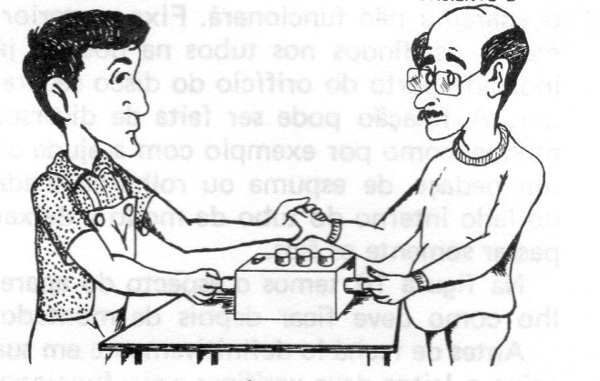
In this case, with the other two hands, experience must be directed towards concentration, relaxation, etc. Environment music can help in the experiment.
This does not mean, however, that the author defends exoteric hypotheses of the manifestation of this "form of energy." The author starts from the point where known and well-established physical principles come into practice. The rest is for each one’s account …
Q1, Q2, Q3, Q4 - BC548 or BC238, preferably - general purpose silicon NPN transistors
D1, D2 - BC315 - general purpose diodes - see text
M1 - 200 uA common VU meter
R1, R2 - 10k x 1/8 W - resistors (brown, black, orange)
P1 - 10 M or 4M7 - potentiometer
P2, P3 - 4k7 - common potentiometers (lin or log)
C1 - 10 nF or 0.01 uF - ceramic or polyester capacitor
C2 - 10 uF x 12V - electrolytic capacitor
S1 - single switch
B1 - 9 V battery
Miscellaneous: mounting box, 1-inch PVC tubes, terminal bridge or printed circuit board, plastic buttons for the potentiometers, etc.


