Obs. This circuit is part of our book originally written in Portuguese and included in the English version Electronic Projects from the Next Dimension.
In particular, we recommend for this project three high-voltage neon transformers that can be found in the US. market and that furnish output voltages between 2,000 and 4,000 V.
One is MINIMAX4, from Amazing Products, a division of Information Unlimited (http://www.amazingl .com/voltage.html). It is rated to 14 Vdc of input voltage and an output of 3,000 to 4,000 V, with current between 5 and 10 mA.
Another device from the same company, but less powerful, is the MINIMAX3 with specified output voltages between 2,000 and 3,000 V.
The third is the NEONXA, also from Amazing Products, and information can be found on the intemet page http://amazingl .com/neondc.htm.(This article was written in 2001).
The main advantage of using these transformers is that the circuit is easy to mount. The reader will only have to add the power supply (or use a car battery or even 8 D cells) and the electrode.
In our project, we are going to power this circuit from a 12 Vdc power supply and plug it into the electrodes described in the previous projects.
As the frequency used for this type of inverter is higher, and the performance is also better than that of the previous project, good photos and images of auras can be obtained.
How It Works
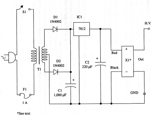
The circuit is formed by a 12 V power supply, the car neon lamp transformer, and the electrode. For the power supply, a simple circuit is given. The ac voltage is lowered by the transformer and applied to a diode bridge.
The low dc voltage after the diodes is filtered by C1 and stabilized at 12 V by the 7812 integrated circuit (voltage regulator).
The 12 Vdc is used to power the car neon lamp transformer that furnishes an output between 3,000 and 4,000 V. This high voltage is applied to the electrodes.
An option for the power supply is the use of a car or motorcycle 12 V battery.
It is also possible to use 8 D cells, or two 6 V lantern batteries wired in series. But because the current drain is high, the life of the batteries is not long when used for this task.
Another option is the use of a 12-14 V power supply plugged to the ac power line (commercial type). Find one rated to 800 mA or more, and observe the output connector polarity (positive or negative in the center as shown in Fig. 1.

Assembly
Figure 2 shows the complete diagram of this version of a Kirlian machine using a car neon light transformer.

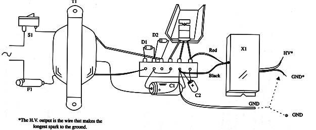
The power supply is the only part to be mounted by the reader. A terminal strip can be used as the chassis for the small components of this part as shown in Fig. 3.

It is important to install all the parts in a box, as we are working with ac power line voltages, which present a real danger of shock if any live part is touched.
We recommend the use of a plastic or wooden box to reduce the danger of shock if any internal part touches it. Do not use a metallic box.
Electrodes
The electrodes are mounted as in the previous project. Use short wires to connect the output of the high voltage transformer to them. The electrodes can be placed on the box.
Testing and Using the Circuit
The neon lamp high-voltage detector can be used to test this circuit. If the circuit is OK, placing the high-voltage detector near the electrode will light the neon lamp.
Connect the ground terminal to a suitable ground source. Turn on S l, powering up the circuit. A “hiss” can be heard if the circuit is operating properly.
This is produced by the high voltage in the electrodes.
In the dark, put your finger on the electrode. If you feel a sensation of being shocked, you need to make some changes in your project, as follows:
1. Replace the plastic or glass on the electrode with a thicker piece.
2. Make sure that the transformer is the correct one and that it is wired as indicated in the project description.
If the circuit seems to work well, you can start with your experiments.
Always wear shoes when making these experiments, and do not touch any metallic object. If plants or other objects with no connection to ground are used in the experiment, connect them to ground with a Wire.
Suggesfions
Use color filters as in the other experiments.
Films sensitive to UV and IR (ultraviolet and infrared) can be used experimentally for registering the images.
Capture the images registered in the photos using a scanner and process them using any suitable computer software.
Semiconductors
IC1 - 7812 integrated circuit, voltage regulator
D1, D2 - 1N4002 or equivalent silicon rectifier diodes
Capacitors
C1 - 1,000 µF/25 WVDC, electrolytic
C2 - 220 µF/ 16 WVDC, electrolytic
Miscellaneous
T1 - Transformer, 117 Vac or ac power line voltage primary; 12 C, CT x 1 A secondary
F1 - 1A fuse
X1 - Automotive neon light transformer, MINMAX4 or NEONXA (see text)
Terminal strip, heatsink for IC1, Wires, fuse holder, electrodes, photographic films, power cord, solder, etc.


