The interesting device described here is a magnetic field converter that can distinguish changes in a magnetic field or pick up modulated magnetic fields and convert them into audible sounds. We might say that this is a device to "hear magnetic fields," and many experiments in paranormal sciences can be devised with its aid.
The circuit is formed by a pickup coil and amplifier stages that drive a small loudspeaker. It is very simple and can be powered from AA cells, making it portable.
Experiments
In ESP experiments, the device can be used to monitor any abnormal signals present near the subject. The magnetic changes in the ambient when the subject reaches the trance state or other mind states can be reproduced as audible sounds.
This type of bioprobe can be used to detect whether, in the location of the experiments, there exist magnetic fields or signals that can cause interference. This is useful in locations where transcendental meditation or biofeedback experiments are made, and in many other places. In radiesthesia experiments, we can monitor the influence of a pendulum on the ambient magnetic field during an experiment.
According to many studies, ghost and spirit manifestations often are associated with magnetic field disturbances. Such disturbances can be detected using this circuit. In EVP experiments, the circuit can also be used to pick up signals from a telephone handset via its magnetic field.
How It Works
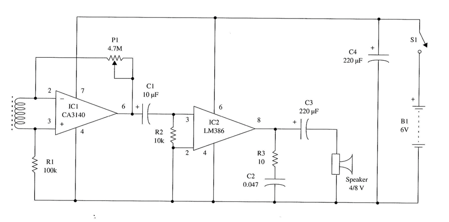
The modulated magnetic field is picked up by the coil, producing a small signal at its output. This signal is applied to the inputs of a JFET operational amplifier wired in the differential mode. The voltage gain of this configuration is regulated by the feedback potentiometer, which can be adjusted from 1 to 47 MΩ.
In the next stage, we find an audio amplifier that can drive a small loudspeaker using the several hundred mill watts of signal coming from the first stage. As the voltage gain is given by the feedback network in the operational amplifier, the volume control has been replaced with a 10 kΩ fixed resistor. The circuit is powered by four AA cells.
Assembly
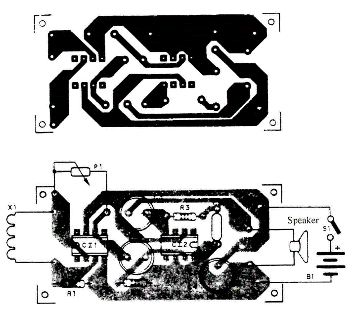
Figure 1 shows a complete diagram of the device. The components are mounted on a small printed-circuit board as shown in Fig. 2.
The pickup coil is the same as described in the previous project. You can also use the primary winding of a small high-voltage or high-impedance transformer without the metallic core.
A small plastic or wooden box can be used to house all the components. Its size is basically determined by the dimensions of the loudspeaker and the battery holder.
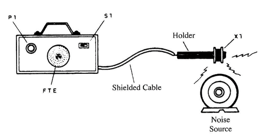
The pickup coil can be installed at the end of a cable as shown in Fig. 3. The cable must be shielded and about 1 to 1.5 m in length. Other components used in the project are not critical, and many of them can be replaced with equivalents that have values near the recommended ones.
Testing and Using the Circuit
Place the cells in the cell holder and turn on S1. Placing the coil near magnetic field sources such as those plugged to ac power lines (motors, solenoids, etc.), the "hum" of the power supply line can be heard.
If the pickup coil is placed near a loudspeaker that is reproducing any sound, the signal will be picked up from its magnetic field (rather than from vibrations in the air, as in the case of a microphone) and reproduced in the loudspeaker of the unit.
Using this circuit is very simple. You only have to place the coil near the source of the magnetic disturbances you want to detect. The gain is adjusted by P1. Avoid locations where the hum of the ac power line can be picked up. Changing the position of the coil, you can find areas where the field lines cut the coil wire at a square angle. In this position, no voltage is induced, and the hum will not interfere with the experiments.
Suggestions
■ Replace R2 with a 10 kΩ potentiometer to add a volume control to the circuit. One end is connected to pin 3, the other to capacitor Cl, and the cursor to pin 3 of the IC.
■ More gain can be added to the circuit if you replace P1 with a 22 MΩ resistor.
■ The tone can be controlled with a capacitor placed between pin 3 and the 0 V line. Values for this capacitor can range from 0.01 to 0.22 µF. The higher the capacitor value, the more you can cut the high frequencies (treble).
■ A photodiode or phototransistor can replace X1. The circuit is thereby trans-formed into a light-to-sound converter.
■ Placing this circuit near the handset of a telephone, the sounds on the line can be picked up and reproduced by the loudspeaker. Experiments involving sounds from the telephone line can be performed.
Semiconductors
IC1 CA3140 JFET operational amplifier, integrated circuit
IC2 LM386 audio amplifier, integrated circuit Resistors
R1 100 kΩ, 1/8 W, 5%—brown, black, yellow
R2 10 kΩ, 1/8 W, 5%—brown, black, orange
R3 10 Ω, 1/8 W, 5%—brown, black, black
Capacitors
Cl 10 µF/12 WVDC, electrolytic
C2 0.047 µF, ceramic or metal film
C3 220 µF/12 WVDC, electrolytic
C4 100 µF/12 WVDC, electrolytic
Miscellaneous
P1 4,700 kΩ - 2 potentiometer
X1 Pickup coil (see text)
SPKR 4/8 Ω, 5 cm small loudspeaker
S1 SPST, toggle or slide switch
B1 6 V, four AA cells
Printed circuit board, cell holder, plastic or wooden box, knob for P1, wires, solder, etc.


