In fact, very low-frequency signals produce short-duration sparks that can cause some sensation of being shocked. If this occurs, replace the glass or plastic in the electrode by a thicker one. It is normal to feel a slight heat or tingling sensation when placing your fingers on the electrodes.
The circuit is powered from the ac power line, and care must be taken when using it to avoid shock hazards. The use of an isolation transformer between the circuit and the ac power line is important.
Important: do not touch any part of the circuit when it is in operation, as it is plugged directly to ac power line! Always use an isolation transformer.
When photographing your fingers or hands, always wear shoes. Allowing your feet to contact the ground directly can increase the currents through your body, causing severe shocks. If you feel a sensation of being shocked, replace the glass sheet with a thicker one.
How It Works
The circuit consists of a relaxation oscillator using a neon lamp and a silicon-controlled rectifier (SCR). The ac power line voltage charges Cl and, at the same time, C2 via R1 and P1. As soon as the voltage across C2 reaches the ignition point of the neon lamp, a conduction pulse is produced and applied to the gate of the SCR.
With the presence of the pulse, the SCR triggers on, closing the circuit formed by C1 and the low-voltage Winding of the ignition coil. This means that C1 discharges via the ignition coil, producing a high-current pulse. In consequence, a high-voltage pulse is produced in the secondary Winding of the ignition coil.
With the discharge of C1 and C2, the neon lamp turns off, and With it the SCR.
A new charging cycle begins, and the described process repeats.
The charge and discharge cycle can be adjusted by P1. With the values shown in the circuit, the oscillator will operate at a frequency between 100 and 1,000 Hz. Reducing C1 and C2 to 1 µF and 0.047 µF, the frequency can be increased, but the output power is lowered.
The high voltage induced in the ignition coil depends on the voltage reached by the Cl charge in each cycle. This voltage can rise to values between 4,000 and more than 30,000 V.
As the current in the secondary Winding of the ignition coil is very low, the high voltage is not life threatening, but it can cause a severe shock to anyone who touches the line. Note that there is no isolation between the power supply line and the output of the high-voltage circuit.
This means that special care must be taken when using the device. For more secure operation, an isolation transformer on the input is recommended.
Assembly
The schematic diagram of the high-voltage circuit for Kirlian photography in its first version is shown in Fig. 1.
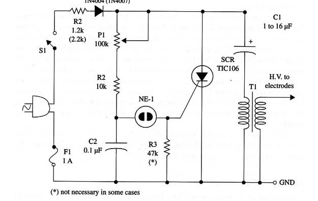
R1 is a wire-wound resistor. This resistor can be altered according to the ac power line voltage. The values in parentheses are for the 220/240 Vac power line. Electrolytic capacitor Cl must have values between 2 and 16 µF. This capacitor determines the amount of energy delivered to the ignition coil in each pulse and therefore the output power of the circuit.
Any ignition coil such as the ones commonly used in cars can be used. All the types will function, and the only difference is the voltage found in the output, which can vary within a wide band of values.
The SCR must be mounted on a small heatsink. A piece of metal can be used as a heatsink. Types With suffix D or E are recommended if you are plugging the circuit into a 117 Vac power line. For a 220 or 240 Vac line, the recommended SCR will have the suffix E.
C1 is any electrolytic or polyester capacitor rated to 250 WVDC or more. If the circuit is connected to a 220 Vac or 240 Vac power line, the capacitor must be rated to 400 WVDC or more.
The circuit must be installed in a wooden or plastic box to avoid contact with living things, which can cause a severe shock hazard. Do not use a metallic box.
T1 is any isolation transformer with a ratio of 1:1. The primary Winding is rated to the ac power line voltage. Output power is rated to at least 20 W.
Warning: Make tests with your multimeter to ensure that the isolation between windings is high enough (2 M ohm or more) to guarantee safe operation of the circuit. Important: See earlier precautions related to safe use of the machine.
The Electrode
A metal plate (copper, aluminum, or other metal foil) with dimensions from 10 10 cm to 15 x 15 cm is placed onto a plastic base or glass base several centimeters larger, as shown in Fig. 2. You can use any glue to affix the electrode, or even adhesive tape.
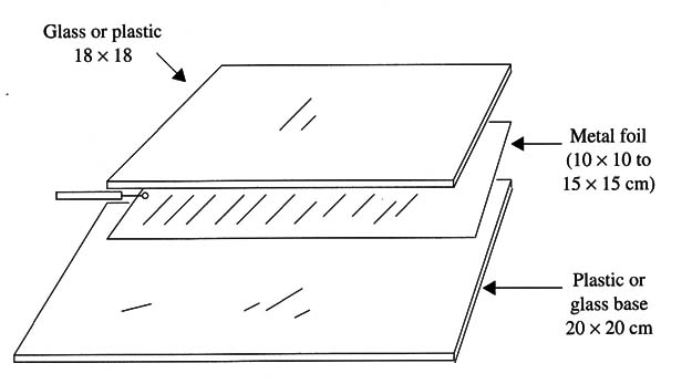
You can use common wire to connect the electrode to the high-voltage transformer if it is not placed at too great a distance. If the electrode is placed far from the circuit, the wire that connects the plate to the circuit must be of a special type as used to connect the high-voltage circuits of TVs. This is applicable to distances above 50 cm. Common plastic-covered wires do not completely isolate the high voltage produced by the circuit and can allow dangerous shocks if touched.
Over the electrode, place a piece of glass or plastic. The thickness of this glass piece depends on the high voltage generated by the circuit. Pieces with a thickness between 4 and 10 mm are recommended. Tests must be made to determine which thickness affords the best results without allowing the sensation of being shocked.
This electrode can be used with all other high-voltage circuits described from here on. Of course, experiments must be repeated in each case to determine the correct thickness of the glass or plastic sheet.
Using a TV High-Voltage Transformer
The ignition coil can be replaced by a horizontal output transformer as found in old analog TV receivers or computer monitors (using CRT). This transformer has some advantages over the common ignition coil in this project.
If you have an old nonfunctional TV (black-and-white or color), you can re- move from it a horizontal output transformer that can be used for the high-voltage electrodes. The high-voltage transformer is used in old TVs and computer monitors to produce voltages between 5,000 and 35,000 V, which are needed to accelerate the electron beam for producing images in the screen of the cathode ray tube (CRT).
You only have to take off the transformer and add 20 to 40 turns of common wire (AWG 22) to the core as shown in Fig. 3.
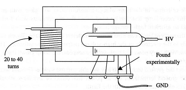
The high voltage to the electrodes is taken from the upper terminal of the coil.
The other terminals correspond to taps in the coil, and you must find the one that gives the best results when attached to the ground.
An important advantage is gained by the use of this kind of transformer as a replacement for the ignition coil: the high-voltage Winding is completely isolated from the circuit and so from the ac power line. You will not need the isolation transformer in this case.
If, when using this transformer, Sparks are produced in the windings and no high voltage is detected at the output, the transformer probably was affected by humidity or has isolation problems. You can try to leave it in a dry place over a period of time to eliminate the humidity and then try again. If this does not work, the transformer can,t be used in this project.
Although this doesn’t eliminate the possibility of getting a severe shock if you touch a high-voltage part of the electrode, the danger of receiving a direct discharge from the ac power line is eliminated.
High-Voltage Detector
A neon lamp can be used to detect the high voltage produced by this circuit and others described in this book. This lamp is mounted at the end of a plastic tube (a spherical pen tube) as shown in Fig. 4.

If you place the neon lamp near the electrode or output of the high-voltage transformer, it will glow with an orange light. This neon lamp test can be used in all the experiments with Kirlian machines as an efficient high-voltage detector.
Any fluorescent lamp can also be used to detect high voltage. Touch one of its terminals to the electrode or the high-voltage output of the transformer. The lamp will glow. With very powerful high-voltage sources, the lamp glows if it is simply near the source.
Connect the ground terminal to any suitable ground source. Ground sources include the ground terminal of the ac power line outlet or any large metal object that makes electrical contact with the earth.
Warning: If the ground terminal is not connected to a proper grounding point, the output power will be reduced, and the results when observing or photographing auras will be inferior. However; when the ground connection is made, the circuit becomes more dangerous as the output power is increased.
Using the Circuit
Initial experiments can be made using common objects and living things such as leaves, coins, paper clips, insects, keys, etc., as samples. Turning on the circuit, you’ll hear the sound of the high-voltage ions escaping from the electrode.
This sound is like a “hiss”. A smell of ozone can be noted during the operation of the high-voltage sources (ozone is produced when three biatomic molecules of atmospheric oxygen are converted into two triatomic oxygen molecules, or ozone).
The aura can be seen in the dark when the samples are placed onto the electrodes.
Adjust P1 to get the best aura. This potentiometer controls the high voltage applied to the electrodes. Don”t touch the electrodes during these experiments, even though you have determined that your project is safe.
To see the aura of your fingers, adjust P1 to get the lowest power (use a coin as sample) and then put your linger onto the electrode. The normal reaction is to feel a little bit of heat.
If you feel a shock, you must replace the glass piece with a thicker one or adjust P1 to reduce the voltage in the electrodes. You can also make changes in the frequency, increasing it to reduce the shock sensation. Adjust Pl'to get the best image without shock.
Important: Take care when making these experiments, as the circuit is wired to the ac power line.
After some experimentation with visual images, you can try to make photos or register the images on paper.
Observation
How the pattern you saw in the dark is registered on'fax paper or in a photograph depends on some characteristics of the Kirlian machine. This circuit produces low-frequency pulses that are responsible for Sparks or bright ion streams leaving the sample.
This means that the image is different from those produced by higher-frequency machines such as described in the following projects. Of course, you can alter the operational frequency as explained below.
Using Fax Paper
Cut a small piece of fax paper (5 x 5 cm or according to the size of the object to be photographed) and place it on the electrode, and place an object on the piece of paper (a coin, for instance) as shown in Fig. 5.
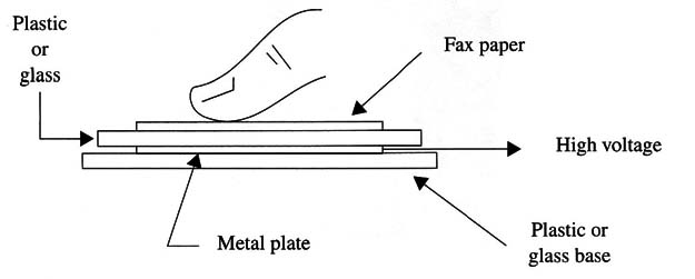
Make sure that the sensitive side of the paper is in contact with the object. If the paper is inverted, the process doesn't work.
Turn on S1 and adjust P1 to get the best performance. You'll see the aura of the object and hear the “hiss” of the charges leaving the object. Wait between 5 and 15 seconds. Turn off the device and reveal the photo. The best time interval will be found experimentally according to the fax paper and the power of the Kirlian machine.
Depending on the paper sensitivity and the output power of the Kirlian machine the image may appear on the paper after an interval of time without the need of any kind of processing. But the image can be enhanced as shown in Fig. 6.
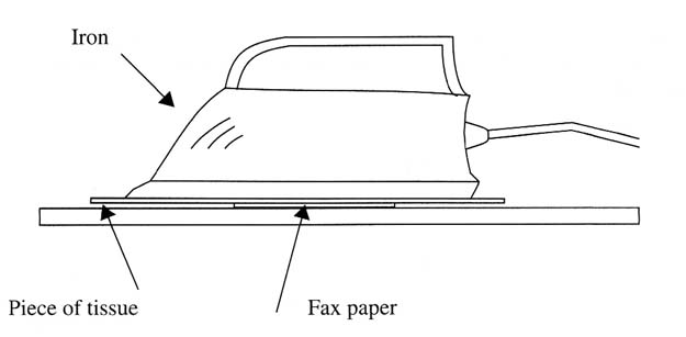
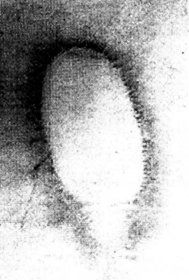
Iron the paper, adjusting the iron to a very low temperature. If the iron is too hot, the image is burned and will appear as a black spot. The time and the temperature must be also found experimentally according to the fax paper, the type of iron, and the temperature. A fax image generated by the author appears in Fig. 7.
Using Photographic Film
Working with photographic film requires some ex- tra care. There are several techniques in use by researchers.
Working in the Dark.
Place a piece of film between the plate and the object to be photographed. If you are photographing your lingers, Fig. 8 shows how the film is placed. Simply place the lilm in the location shown for the fax paper.
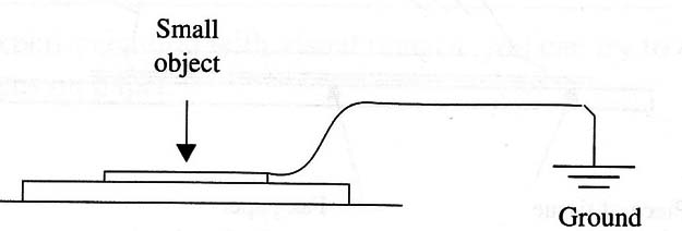
Turn on the high-voltage circuit (Kirlian machine) for 3 to 20 seconds. The best time interval will be determined by experimentation and can vary according the sensitivity of the film and the output power of the circuit.
When photographing metallic objects such as a coin, or living protoplasm as a leaf, it is important to install a ground electrode as shown in Fig. 8 to increase the current and the corona effect.
After exposure, the film must be placed in an opaque, light-proof envelope before you can turn the lights on again. The film is ready for development.
As the output power of each circuit can vary within a large range as determined by the components’ tolerances, and the film characteristics can affect the image, the experimenter must make several photos to find the correct exposure time and adjustment of P1.
Working in the Light.
It is possible to make photos under ambient illumination if you protect the film with opaque cards. In a dark ambient, place the piece of film
between the two opaque cards or in a light-proof envelope. Then, in the ambient light, you place the envelope containing the film between the object and the electrodes as shown by Fig. 9.
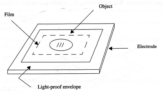
Turn on the high-voltage generator and expose the film from 3 to 30 seconds to register the image. Turn off the device and process the film. Depending on the film sensitivity (ASA or DIN), the correct exposure time will vary and must be determined experimentally.
Using Polaroid Film.
Polaroid film provides another good option for producing Kirlian photos or small objects.
- Working in the Dark. The room where the experiment is made must be totally dark. Place the film on the electrode, and on the film place the object to be photographed (& coin, your finger, etc.).
Turn on the circuit (which should already have been adjusted to give the best results with the object to be photographed When viewing the images) for a time duration of 1 to 10 seconds. Again, the correct interval must be found experimentally, as it depends on the circuit characteristics (which change with the tolerances of the components) and the sensitivity of the film. Polaroid films such as the 600, SX-70, or Time Zero are good. We observe that Polaroid 600 is not a high-definition film and will result in blurred images.
After exposing the film, place it back in the camera (in the dark) and take a photo pointing the camera at any dark place. (Do not use a flash.) Then, wait for the print to be ejected from the camera.
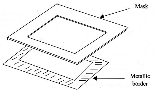
Caution: Polaroid have a metallic white border that is conductive, causing ares and electric shocks if touched. When using these films, cut a window in a piece of plastic to make a mask as shown in Figure 10.
Working under Normal Light.
You can use your Polaroid camera to expose the film by putting it inside a light-proof wood or cardboard box. This box must be large enough to encase the Polaroid camera and have some additional space for working with the film.
Using a black or very dark fabric, make two sleeves with elastic on one end, similar to coat sleeves. The sleeves are attached to two holes made in the box. Use staples, glue, or other suitable means to fix the sleeves.
It is important to make the sleeves and holes light tight. You can handle the film inside the box, putting it on the electrode and then placing the object to be photographed on top of it. If you are trying to photograph your fingertips, put it on the electrode. Turn on the Kirlian machine for 1 to 10 seconds, according to the film speed. Then, place the film in the camera and take a photo in the dark as before so that the print is ejected.
You can also use this dark box to insert film into a light-proof envelope. You then take it out of the box, take the photo, and place it back into the box for later processing.
Suggestions
Use color filters between the film and the object to be photographed. Try filters created by your imagination such as color cellophane pieces and filters such as the ones described for EIP experiments (see this section in the site).
Photo films that are sensitive to UV (ultraviolet) or IR (infrared) can be used for experimentation. It is worth noting that a wide assortment of filters and op tical materials can be purchased from Edmund Scientific Corporation (web site http://www.edsci.com).
Test other kinds of light-sensitive materials such as photostatic paper. The im- ages of auras can also be seen with the aid of night-vision binoculars.
Scan the images and process them using a computer. Many programs can be used to process the images, revealing details not seen in the original images.
The frequency can be increased by reducing Rl and Cl. (The lowest recommended value for R1 is 470 ohm in the 117 Vac power line and 1 k ohm in the 220/240 Vac power line.) The value range for Cl is given in the parts list.
Photographing Small Objects.
If small objects are placed on the electrode of a Kirlian machine, they can,t produce a good photo unless they are connected to ground. To connect the objects to the ground, you may use a wire with alligator clips on the ends. In the case of a leaf, choose a specimen that is no bigger than half the size of the electrodes (2.5 to 5 cm long).
Connect the ground wire directly to the tip of the stem or leaf. Use an alligator clip for this task (try to find an alligator clip that does not press too hard on the leaf, cutting its tip). Cover the leaf with a small piece of glass or plastic to hold it flat on the film. Experiments will show you how long you have to power up the circuit and how much pressure must be exerted on the leaf to get a good image.
If you are photographing a coin, the plastic or glass cover is not required, since the coin is heavy and Hat enough to lie as desired on the electrode.
Interferences.
Many of the circuits described herein can radiate spurious signals in the radio spectrum used for communication services such as TV, radio, etc., interfering with many communication devices. To avoid interference, do not use the Kirlian machines near such equipment.
The Phantom Leaf.
One of the most important phenomena found by Kirlian photography is referred to as the “Phantom Leaf Experiment.” Cut about 2 cm off the tip of a leaf and photograph it. If you are lucky, you7ll get an image of a whole leaf, even though the tip is missing!
Semiconductors
D1 1N4004 or equivalent silicon rectifier diode (use the 1N4007 in 220 or 240 Vac power lines)
SCR TIC106-D silicon-controlled rectifier
Resistors
R1 1,200 ohm or 1,500 ohm, 10 W, Wire-wound resistor (2,200 ohm x 10 W if the circuit is used in a 220/240 Vac power line)
R2 10 k ohm, 1/8W, 5%-brown, black, orange
Capacitors
C1 1 to 16 pF/250 WVDC, electrolytic or metal film (see text for the 220 or 240 ac power line)
C2 0.1 µF/ 100 WVDC or more, ceramic or metal film
Miscellaneous
F1 1 A fuse
NE-1 NE-2H, any common neon lamp
P1 100 k ohm potentiometer
S1 SPST, toggle or slide switch
T1 Ignition coil or high-voltage TV transformer (horizontal transformer) (see text)
Printed circuit board, plastic or wood box, knob for Pl, wires, electrodes, solder, etc..


