Note. This article was originaly published in Popular Electronics em a 1998 edition.
Circadian rhythms, the study of the internal biological clocks of various living organisms, have been the subject of scientific research for some time now.
Studies have shown the internal clocks of living organlsms to be sensitive to light, as well as to other forms of external stimuli (such as ultraviolet, infrared, and nuclear radiation, magnetic and electric fields, etc.) that can a?ect hormonal levels and other physiological functions (see Fig. 1).
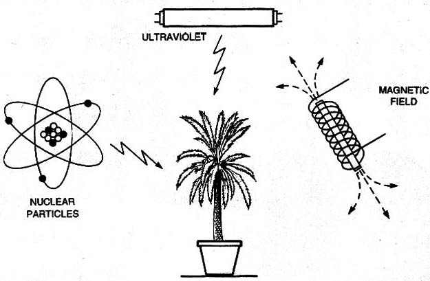
Thus, it follows that by subjecting living organisms to various forms of external stimuli and observing their reactions, scientists can extrapolate how various external forces can a?ect changes in growth, physiology, reproductive functions, etc.
Such scientific inquiry needn’t involve elaborate, high-tech (read high-priced) laboratory equipment, facilities, and conditions.
Such studies can be pursued using common, fast-growing, domestic vegetation (such as tomatoes, beans, corn, flowers, etc.) as subjects.
A dark roorn or a cardboard box can be used as a controlled environment wherein the subject (in this case a plant) can be bombarded with various forms of artificial stimuli as shown in Fig. 2.
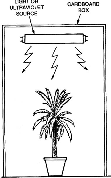
For example, a coil fashioned on a cardboard form can be used to produce magnetic fields with which to conduct radiation experiments. (see Mini Projects in this site to a magnetic field source)
Exposing several plants to di?erent sources and levels of radiation allows the researcher to gain an understanding of how growth and development are influenced by external forces.
Of course, in order to get meaningful results, the researcher must use two subject groups for the experiments.
One group-serving as the control group-can be exposed to the light following the normal day/night cycle.
The second group might be exposed to di?erent forms of radiation (modulated light, ultraviolet, infrared modulated, pulsed light sources), or the usual day/night cycle might even be reversed.
The researcher then can compare the growth and development of the two groups.
Experimentally Yours. As all of the experiments outlined herein are conducted using common, readily available subjects and equipment (such as lncandescent or fluorescent Iamps) the experimenter needs no special background in behavioral studies to perform this scientific research.
ln addition, the subjects can be exposed to light. Radiation and magnetic fields slmultaneously to perform complex experiments.
For our studies we've selected an assortment of practical electronic circuits that can be used to discover how the circadian rhythms of various plants and insects are affected by environmental changes.
The selected circuits can produce light, ultraviolet radiation and magnetic fields in several patterns that can be adjusted to various operating conditions.
The clrcuits can be used to study the effects of external forces on plants or other living organisms, such as insects or even humans (with specialized aid).
Of course, we're certainly not advocating that you put a human being in a coil and crank up the "juice" to observe what happens when a magnetic field is produced.
But, a trial that involves stress would certainly make an interesting experiment in psychology.
For example, you might put several volunteers in a darkened room with a pulsed light to cause stress and then measure respir'ation, heart rate and blood pressure. (Sessions of about 10 minutes are sufficient) .
By repeating the experiment (with the same group), you can determine lf the subjects become more or less affected by unusual ambient conditions.
Now let's take a look at a few circuits that can be used in your quest for knowledge.
Stroboscopic Lamp. Our first circuit.see Fig. 3, is a simple arrangement that's comprised of four i-amp 400-PIV rectifier diodes (Dl -D4), four resistors (three fixed and one variable), a capacitor (C1), an lncandescent lamp (ll), and an SCR.
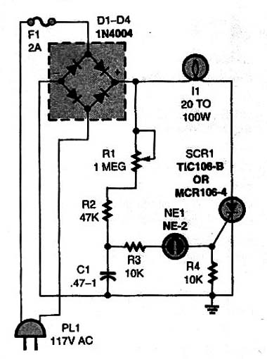
The pulse rate of the circuit can be adjusted (Via Rl) over a wide frequency range, from about four pulses per second (4 Hz) to one pulse every five seconds (approx. 0.2 Hz)
A single capacitor, C1, sets the overall operating-frequency range of the circuit.
The range of frequencies produced by the circuit can be altered by substituting different capacitor values for C1.
The circuit, which can be used to drive common incandescent lamps rated up to 100 watts (do not use other type of lamp), is simple enough to be assembled using any construction technique with which you are most comfortable.
When assembling the circuit, the SCR should be mounted to a heatsink to dissipate heat generated by the SCR during operation.
When mounting the circuit in an enclosure, take care that any exposed parts of the circuit are kept away from any conductive surface.
Day/Night Conditioner. Our next circuit takes a slightly different approach to the exploration of circadian rhythms.
The circuit shown in Fig. 4 Is designed to help the amateur researcher ascertain the effects of artificially altering the test subject’s 24-hour (day/night) cycle using a common low-voltage incandescent lamp.
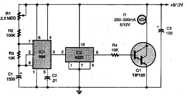
The circuit, built around a 555 oscillator/timer (lC1), a 4520 dual synchronous up counter (IC2), TIP120 Darlington transistor (Q1), and an assortment of support components, can be set for a flash rate ranging from several mlnutes to more than 24 hours.
In the Day/Night conditioner, the 555 (IC1) is configured as an astabie multivibrator (or oscillator), the frequency of which is determined by R1, R2 R3 and C1.
Potentiometer R1 a 2.2-megohm unit, allows the oscillator output to be adjusted over a wide range of the frequencies.
The output of the oscillator is fed to the ENABLE input of up counter K32 (only half of which is used in this application) at pin 2, while lC2’s CLOCK input (at pin 1) is tied low.
The output of the counter is fed through a 10k resistor (R4) to the base of Q1 .
Each time the counter output goes high, the Darlington transistor (Q1) turns on, completing l1's ground return path, causing the lamp to light.
During negative exoursions of the output waveform, It is cutoff.
When assembling the circuit, Q1should be mounted to a heatsink.
The Darlington transistor can be replaced by a power-FET, such as the lRF540, without any additional alteration in the circuit.
The circuit can be powered from a 6- or 12-volt power source.
The lamp (L1) can be a 6- or 12-volt incandescent unit depending on the supply voltage selected.
The lamps can be placed in a cardboard box along with the subject (plant or insects) to be studied.
Controled Duty-Work Light-Source.
Figure 5 shows another circuit that can be used for circadian-rhythm experiments.
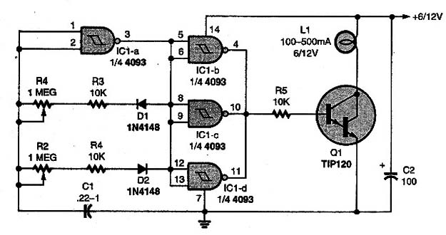
The circuit, built around a 4093 quad two-input NAND Schmitt trigger, allows both on-time and off-time periods to be controlled.
In that circuit, one gate from lC1 (lC1a) is configured as an astable oscillator, whose duty-cycle can be adjusted via R1 and R2.
The setting of potentiometer R1, along with the fixed-resistor value of R3 determines the charge period of C1 and, by extension, the time that lCl as output is at logic high.
The setting of potentiometer R2, along with the value of fixed-resistor R4, combine to determine the discharge period of C1.
It also determines, in an analogous way, the time the transistor-as well as the lamp-is on.
The other three gates (lC1-b, lC1-c, and lC1-d), which are connected in parallel, are used to boost the output drive current of the oscillator, while inverting the signal.
That means that when the output of lC1-a is high, the combined outputs of lC1-b, lC1-c, and lC1-d are at logic low.
That logic-low output, which is applied to the base of transistor Q1, holds the transistor at cutoff, so the lamp does not light.
However, when the output of the oscillator swings low, the combined output of the three parallel NAND Schmitt triggers (lC1-b, lC1-c, and lCi-d) goes positive.
That positive output causes Q1 to turn on, illuminating It.
The clrcuit-which is capable of driving lamps up to 600 mA-can be powered from (6- or 12-volt supplies.
The circuit in Fig. 5 can be altered, as illustrated in Fig. 6, thereby allowing the reconstituted circuit to control a lamp that’s powered from the AC line.
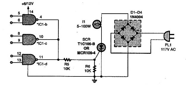
The circuit can drive lamps up to 100 watts.
As the SCR may be required to dissipate considerable heat, that unit should be mounted to a heatsink.
Fluorescent UV Light-Source.
Our next circuit (see Fig. 7), although nearly identical to the circuit in Fig.5, is designed to produce short pulses of visible light or ultraviolet radiation.
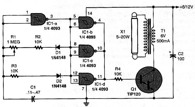
The only difference between this circuit and the one in Fig. 5 is that instead of directly driving a fluorescent lamp, the output of the transistor is used to drive a step-up transformer (T1) which, in turn, provides sufficient voltage to light a fluorescent lamp (X1).
The lamp's flash rate is determined by the RC time constant established by R1 and C1.
The flash rate can be altered by varying the value of C1 within the range indicated in Fig. 6.
Transformer It is a common power transformer, whose primary winding (rated at 117 volts AC) is connected as the secondary and its secondary winding (which can be either 6 or 12 volts at 800 mA) is connected as the primary winding.
That allows Tl to function as a step-up transformer, boosting the low-voltage pulses produced by the oirouit to a level that’s strong enough to ionize the gas inside the fluorescent lamp.
The high-voltage output of the transformer, pulses that can reach up 400 volts, is sufficient to cause even very weak lamps to glow.
Common white, colored, or even ultraviolet lamps (ranging between 6 and 25 watts) can be driven by the circuit in Fig.7.
When experimenting with ultraviolet radiation, do not look directly at the lamp!
The radiation can seriously damage your vision. Ultraviolet experiments should be performed with the lamp enclosed in a cardboard box, as illustrated in Fig. 8.
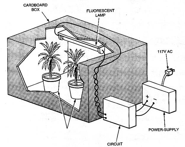
Caution: The high voltage produced by the transformer can cause severe shock.
Make sure that the transformer is isolated from all conductive surfaces when mounted into its enclosure.
Power Supply. All the circuits, intended for long operation periods, should be powered from power supplies and not batteries that can be drained in a short time.
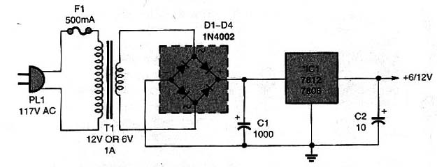
Figure 9 shows a power supply that can be used to power 6- or 12-volt projects that need currents up to 1 amp.
The IC should be mounted on a heatsink. The transformer should have a secondary wounding rated at 1 amp.
The reader should take care when mounting the transformer, as its primary winding is connected directly to the AC power line.
An accidental touch when in operation can cause severe shocks.


