The apparatus we describe measures the ionization, allowing comparisons between environments to detect whether or not the cause of a malaise in a location is due to the presence of electric charges in the air or objects.
Basically, the device consists of a sensitive electroscope with a field effect transistor which has a sensor to indicate if there is charge in the air. A screen or board works as an electrode capturing the charges and thus enabling indication on an instrument.
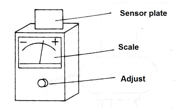
In Figure 1 we have a suggestion of the assembly of the apparatus in a plastic box which facilitates its use in any place.

Thus, it is sufficient to zero the instrument by connecting its sensor for a moment to the ground and adjusting its control so that the reader can then indicate the presence of positive or negative charges by the deviation of the needle in the indicator instrument from the center of the scale.
The device is powered by a 9 V battery and has very low power consumption.
How it works
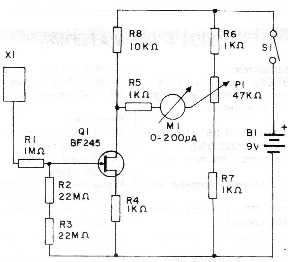
In Figure 2 we have the complete diagram of the environment ionization indicator.

An indicator instrument of the microammeter type, preferably with zero at the center of the scale, is connected to a Wheatstone bridge circuit.
In one of the branches of the bridge we have a field effect transistor whose conduction depends precisely on the electric voltage applied to its gate electrode.
The field-effect transistor is extremely sensitive, with a very high input impedance, which means that if you connect a metal plate to its gate, any electric charge absorbed by this plate will affect the transistor in order to change its conduction.
Of course, this change will cause the bridge to become unbalanced and this will be indicated by the current in the instrument.
A potentiometer connected to this bridge allows its equilibrium point to be easily adjusted depending on the characteristics and tolerances of the components used. This way, by acting on the potentiometer we can balance the bridge and thus zero the instrument.
Two very high-value resistors connected to the field-effect transistor gate become polarized, slowly draining the charges captured by the sensor plate to prevent "locking" the circuit with a false indication.
Assembly
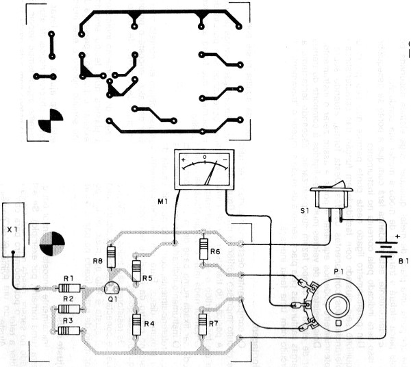
The components of this assembly can be installed on a printed circuit board as shown in Figure 3.

The position of the field effect transistor must be observed because if it is reversed the unit will not operate.
The sensor is nothing more than a metal plate of 10 x 10 cm which can be fixed in a plastic base or in the box of the apparatus itself.
The indicator instrument is a common 0-200 uA microammeter or, preferably, with zero at or near the center of the scale of 50-0-50 uA. For a common microammeter we will place a zero in the center of the scale and make the adjustment of the needle at this point in the balance of the bridge.
The resistors are all 1/3 W and for power we use a clip that plugs into a common 9 V battery, observing its polarity.
The adjustment is made by means of a potentiometer ich which will be accessible through a button fixed in the panel of the apparatus.
Set and Use
Initially lean the sensor on any object in contact with the ground (a faucet, for example). If you are barefoot, place your finger on the sensor as long as you are on the cement floor to get the load reference.
Set the potentiometer to zero the indicator instrument.
By rubbing a comb or a plastic ruler in a synthetic fabric approaching the sensor to the comb, the needle will deflect indicating the presence of a positive charge. The movement of the pointer in the opposite direction indicates the presence of negative charges.
Once the operation has been carried out and this adjustment has been made, it is enough to take the device to the environment to be monitored and observe the position of the needle after a few minutes. Using the appliance some time later, in order to compensate for the variations of the battery voltage by wearing it, make the zero adjustment again.
Semiconductors:
Q1 - BF245 or equivalent field effect transistor
Resistors (1 / 8W, 5%):
R1 - 1 M ohm - brown, black, green
R2, R3 - 22 M ohm - red, red, blue
R4, R5, R6, R7 - 1k ohm - brown, black, red
P1- 47 k ohm - potentiometer
R8 - 10 k ohm - brown, black, orange
Miscellaneous:
M1 - Microammeter - see text
S1 - Single switch
X1 - Sensor - see text
B1 - 9 V - battery
Printed circuit board, assembly box, battery connector, metal plate for sensor, wires, welding, etc.


