Note: for the components used and the utility, it is a fairly current device that can even be improved with a microcontroller control with temperature sensors.
The basic idea of the project is very simple: to use the electric power developed in a resistor to heat a small environment, or the roots of potted plants or containers of experiments.
Resistors are associated in numbers of 3 to better distribute the heat, and their value is calculated so as to maintain the temperature a few degrees above room temperature, thus ensuring the "well-being" of the plant.
We give 5 power options or temperatures depending on the desired applications, and for each of them we have an adjustment which allows two degrees of heating: in one degree we have the total power and in the other, approximately half of it.
The proiect
The range of powers chosen is between 5 and 25 watts - which is enough for a greenhouse or environment of a few cubic decimeters of volume.
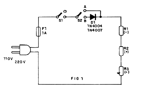
We then use three wire resistors connected in series (R1, R2, and R3). When we connect these resistors to the network, the energy is transformed into heat, being transferred to the environment. With this you can have a temperature rise that will just depend on the value of this component.
The "dissipated power" (P) is calculated as a function of the total resistance (R) and the applied voltage (V) by the following formula:
P = V2 / R (Law of Joule)
By setting V to 110 V or 220 V, as the case may be, we can easily calculate the total value of R for 5 powers. resulting in the following table:
| R (R1 + R2 + R3) | 110 V | 220 V |
| 5 W | 2 420 | 9 680 |
| 10 W | 1 210 | 4 840 |
| 15 W | 806 | 3 226 |
| 20 W | 605 | 2 420 |
| 25 W | 484 | 1 936 |
As we use three resistors, these values must be divided by three and approximate of the commercial series, taking into account the dissipations, that is, the sizes of the components.
We arrive at the following final table:
| R1 = R2 = R3 (ohms) | 110 V | 220 V |
| 5W | 820 x 5W 3k3 x 5W | |
| 10 W | 390 x 10W | 1k5 x 10 W |
| 15W | 270 x 10W | 1k x10W |
| 20 W | 220 x 10W | 820 x 10W |
| 25W | 180 x 15W | 680 x 15W |
The diode works to halve the power supply in the system, thus having a reduced power position.
Assembly
In Figure 1, we have the complete circuit of the apparatus.

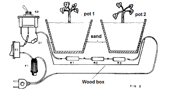
In Figure 2, we have the suggestion of assembly. S, S2, D1 and the fuse must be attached to a housing.

The resistors are buried in a dry sandbox where the vessels are placed. See that there should be no penetration of moisture in the sand, as this would cause an electrolytic attack to the terminals of the resistors, which would be corroded.
In the case of a greenhouse, the resistors may be stuck on its side.
The power chosen will depend on the elevation of the desired temperature and the size of the heated environment. Make experiments.
R1, R2, R3 - wirewound resistors (see text)
F1 - A fuse
D1 - 1N4004 or 1N4007 - silicon diode
S1 - Single switch
S2 - 1-pole wrench x 2 positions or 2-pole x 2 positions
Miscellaneous: an assembly box, fuse holder, wires, welding etc.


