One way to achieve total relaxation is by diverting our attention from our thinking to some kind of repetitive activity which allows us to forget about problems or to divert attention to ambient sounds or lights or any other dispersive activity.
This can be achieved with some kind of activity which forms a closed cycle with our senses, as shown in Figure 1.
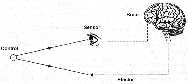
This cycle, as we can see, is closed by a feedback loop which can have the most diverse natures including the one that makes use of electronic resources.
A simple way to have a biofeedback with electronic resources is through a circuit that, by the pressure of the fingers on transducers, can control the brightness of a lamp, as shown in Figure 2.
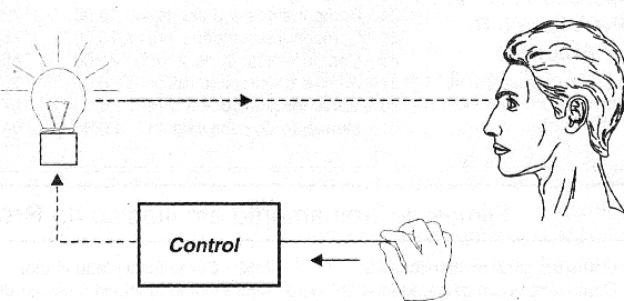
The person involved in the relaxation process should then act on the sensor so that the lamp has a certain brightness pattern that is pleasing to it, for example, similar to that of another lamp that is placed next to the first one used as the standard.
The action of the person on the circuit which controls the lamp has by feedback the light signal that is captured by his/her eyes, which act as sensors, closing the cycle.
The circuit we propose in this article is interesting because it uses sounds that are played on a pair of headphones, as shown in Figure 3.
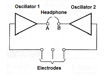
The headphones reproduce different patterns of tones or pulsations that must be balanced by the pressure of the person's fingers on the electrodes.
This way, the effector circuit is part of the person's brain, passing through the muscles which activate the fingers and goes via the sensor to the circuit that produces sounds.
The feedback is the output of the sound circuit that passes through the handset and, via the ears, goes back through the auditory nervous system to the brain, closing the circuit.
Concentrating in the sense of obtaining the balance between the produced sounds the person can achieve states of relaxation, and others that are taught by diverse techniques mainly the oriental ones.
If the reader likes the subject and wishes to have a biofeedback, the simple and harmless circuit we propose can be very interesting and useful in his/her experiments.
HOW IT WORKS
The circuit is made up of two oscillators with common low cost transistors which are connected in a complementary direct coupling configuration.
The frequency of these oscillators depends basically on the values ??of the capacitors of the feedback loop and also the polarization resistors.
In our case, the resistances are basically determined by two potentiometers (one for each oscillator) P1 and P4, and also by the skin resistance of the person holding the electrodes.
Thus, pressing or relieving the pressure on the electrodes alters the resistance of the circuit and with this it is possible to change the frequency of the oscillators.
The idea is to balance the circuits so that the frequencies are equal and have the same tone on both headphones, which requires good concentration and self-control, thus, the total relaxation of the person.
The circuit is designed to operate with two frequency ranges, allowing the reader to find the condition which best suits them for operation.
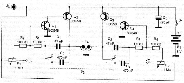
With the switch S2 open, the capacitors placed in the circuit are of low value (47 nF of C1 and C3) which leads the circuit to a production of tones in the audio track.
The user should then try to match the two tones.
With the switch S2 closed, the capacitors C2 and C4 are placed in the circuit by increasing the feedback capacitance and thereby considerably lowering the frequency of the oscillations.
As a result, we will have very low pitched tones or even intermittent pulses.
The user should then seek to synchronize the low pitched tones or synchronize the pulses produced by the apparatus, which will also require great concentration in the sense of dosing the pressure on the electrodes.
In order to have the ideal sound level, which does not disturb, since it is constant, we have a volume control formed by two potentiometers.
The use of separate potentiometers is justified by the possibility of people with different sensitivities in both ears wishing to use the appliance.
The circuit is powered by only two common batteries, with relatively low consumption which allows them to be built in a very compact box.
This makes the device fully portable.
ASSEMBLY
In Figure 4 we have the complete audio-biofeedback diagram.
The arrangement of the components on a small printed circuit board is shown in Figure 5.
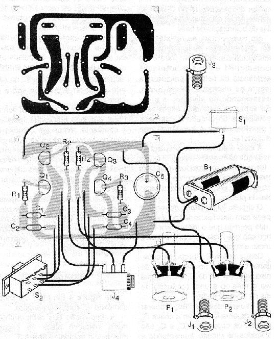
Because it is a fairly simple assembly and uses only transistors, the less skilled readers can even perform it based on a universal board or even an isolated terminal bridge.
The resistors are all 1/8 W or larger and the capacitors can be both ceramic and polyester.
The only electrolytic capacitor is C3 which must have a working voltage of at least 6V.
Although the transistors admit equivalents, it will be interesting that they are of the same type indicated in the list for greater ease of obtaining balance of the circuit.
The headset can be the same as the one you use on your MP3, portable radio, or other stereo, as long as it's the stereo type.
The output jack used on the appliance must be of the same type as the plug of the handset.
The potentiometers are common linear or logarithmic and appropriate batteries must be used to power and the reader must pay attention to their polarity at the time of connection.
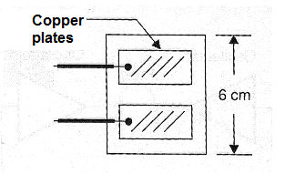
The electrodes may be nailed or bolted metal plates on a base on which the hand or fingers are to be supported, as shown in Figure 6.
Another possibility of electrode is shown in Figure 7 and consists of two common spent cells or metal tubes which must have their ink scraped.
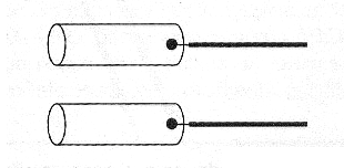
In this case, the third (common) electrode should be a metal plate on an isolated base on which the person should support the bare feet.
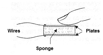
There is also to be made pressure electrodes with conductive sponge of the type found in packages of integrated circuits.
Two metal plates, as shown in Figure 8, are attached to the faces of this sponge whose conductivity depends on the pressure we make in order to compress it.
It is important to note that the current that passes through the person's body when the device works, millionth of an amp and causes absolutely no sensation and presents no danger of shock.
The skilled reader can create other electrode configurations depending on the type of activity he/she want.
TEST AND USE
To test the device, simply place the handset in the ear, put batteries in the holder and press S1.
Leaving S2 open and touching the fingers at the same time at terminals J1 and J2, or even interconnecting them with a wire and turning P1, we must hear sound on one of the headphones.
P2 must be in the highest volume position.
Similarly, by touching J3 or by interconnecting it with J2 we must obey a tone by rotating P4.
In this case, P3 must be all opened.
Closing the switch S2 should have the production of interval pulses when 1 or P4 are in the position of maximum resistance.
To use, simply place the S2 switch in the position corresponding to the chosen effect and then hold the electrodes.
Initially we set P1 and P4 to get close to a situation of balance of sounds and P2 and P3 to the most pleasing volume in the handset.
Then we try to control the pressure of the fingers or hands on the electrodes, concentrating as much as possible, in order to achieve a balance between the sounds produced.
Semiconductors:
Q1, Q4 - BC548 or equivalent - general purpose NPN transistors
Q2, Q3 - BC558 or equivalent - general purpose PNP transistors
Resistors: (1/8 W, 5%)
R1, R3 - 1.2 k ohm - brown, red, red
R2, R4 - 100k ohm - brown, black, yellow
P1, P2 - 1 M ohm - potentiometers
Capacitors:
C1, C3-47 nF - polyester or ceramic
C2, C4-470 nF - polyester or ceramic
C5 - 470 uF / 6V - electrolytic
Several:
S1 - Single switch
S2 - switch – 2 poles x 2 positions
B1 – 3 V - two small batteries
J1, J2, J3 - insulated terminals
J4 - Stereo headset jack - see text
Printed circuit board, electrode material (see text), support for two small batteries, wires, welding, etc.


