Obs. The article is from 1992, but the concepts are current and the assembly can still be elaborated easily.
Negative ions act on people to modify their sensitivity and even reduce the problems caused by certain allergic diseases.
Research has revealed that the presence of negative ions in the air or in the environment causes relief in people suffering from allergies or even burning pains, while positive ions have the contrary effect, aggravating allergy problems, making people more irritating and even making them feel burns or fractures with more intensity.
Perhaps in this fact lies the ability of people who have old wounds, of detecting the approach of heavy rains, when the air "becomes charged" with positive electricity and with that causing certain irritations or aches.
The term "I feel it in my bones" the approach of weather change has therefore a scientific reason.
Small appliances that continuously release negative ions into the air can be purchased in the United States and other countries, and are indicated to people who have any of the problems listed above.
Of course, it is not every case that you can be dealt this way, and a doctor's opinion should always be heard first.
In modern homes and offices where the presence of carpets work as electrifiers, they generate a lot of positive (irritating) electricity, the use of a negative (soothing) ionizer may be interesting.
Small plates used n shoes, which have been trendy in Brazil, used to discharge the positive electricity accumulated in the body and therefore causing relief in people, also have their reason for being.
The design that we present in this article is a simple small ionizer which works to produce a certain amount of negative ions that, released into the environment automatically, without the need for fans or other similar devices.
The circuit consumes very little power (less than 10 watt), and is powered by the local network, which means that its connection permanently does not cause appreciable increase in anybody’s energy bill.
The components used are easy to obtain and simple to build, with no critical adjustments.
CHARACTERISTICS
Supply voltage: 110/220 VAC
Power consumed: less than 10 W
Voltage of ion production: 3 000 to 10000 Volt.
HOW IT WORKS
To generate the very high voltage we need to produce ions, we start from an inverter circuit based on a relaxation oscillator with an SCR.
Thus, the voltage of the network, after rectifying charges the capacitor C1. The value of this capacitor will determine the intensity of the ion flow and may be between those indicated in the diagram.
At the same time C2 is charged via P1 and R2 until the ionization voltage of the neon lamp is reached, around 80 volt.
When this voltage is reached, the lamp drives and the capacitor C2 is discharged by triggering the SCR.
With the SCR firing the C1 armatures, which should be almost at their maximum load, they are short-circuited through the primary T1 winding.
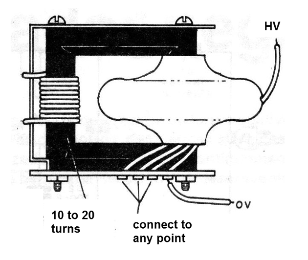
T1 is a high voltage transformer, a flyback, harnessed from an old television set.
With the strong current of its primary, a high voltage pulse is induced in the secondary. As this pulse corresponds to the extension and contraction of the lines of force of the magnetic field which it corresponds to a complete cycle of alternating voltage and should be ratified if we want to have only the negative polarity at the output.
This is achieved with the help of a high voltage rectifier diode (MAT) of the type found in televisions and which is connected to a high voltage capacitor.
This capacitor, Cx, can be built with two aluminum sheets glued on both sides of a common glass board, as shown in Figure 1.
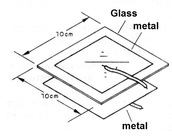
The accumulated voltage in the capacitor allows that at the ionization tip there is a constant flow of ions being produced.
The emission of ions occurs by the effect of the tips. A very high tension applied to a needle causes the charges to accumulate more at the tips and from there they are expelled into the ambient air (Figure 2).
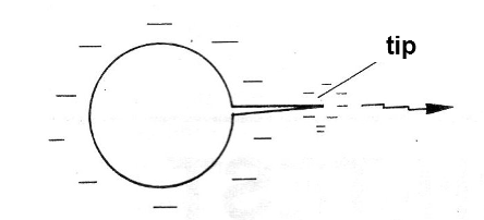
If the charge flow is intense, as in this case, in the dark we can see a slight bluish fluorescence and even hear a "fry" noise.
This tip is the one that must be exposed to the environment and where the ion from the device will be launched.
ASSEMBLY
We begin by giving the complete diagram of the ionizer in Figure 3.
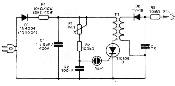
The components can be easily installed on a printed circuit board, except for the flyback, capacitor Cx and the ionization tip, as shown in Figure 4.
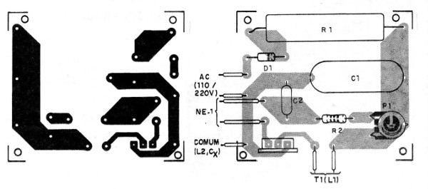
The resistor R1 should be a wire with 10 W dissipation, and built away from the board as it tends to slightly heat during operation.
The values of the components in parentheses are for the 220 V network. The flyback is of any type, the primary winding (L1) being made with 10 to 20 turns of common wire, as shown in Figure 5.
C1 must be metallized polyester with a working voltage of at least 400 V. Electrolytic capacitors for voltages above 400 V may also be used.
The SCR must be of suffix D, considering the high voltage of the generated pulses, but it does not need to be fitted with a heat radiator.
For D2, any high voltage rectifier diode, such as those used in TV, can be used.
The resistors R2 and R13 are 1/4 W and C2 can be polyester to 100 V or more.
X1 is a simply pin that can be welded on the flyback high voltage wire.
The entire assembly can be inserted into a plastic box having only X1 out. The neon lamp may also be visible as it lights on when the appliance is in operation.
The polarity of D2 in the assembly is very important because it determines whether the ions will be positive or negative.
TEST AND USE
Turn on the circuit and be careful not to touch X1 or high voltage wires.
Then adjust P2 until the hiss on the tip of X1 becomes more intense or a slight blue fluorescence appears.
Approaching a neon lamp to the tip, it should light up, indicating the high voltage output.
A fluorescent lamp should also turn on if touched on this component.
Once the operation is confirmed, simply close the device and install it in the desired location.
Be careful not to leave the X1 tip within reach of people, they can suffer strong shocks if they accidentally touch it.
Semiconductors:
SCR - TIC106D - Silicon Controlled Diode
D1 - 1N4004 (110 V) or 1N4007 (220 V) - silicon diode
D2 - TV-18 or equivalent - high voltage rectifier diode
Capacitors:
C1 - 1 to 5 uF x 400 V - electrolytic or polyester
C2 100 nF x 100 V - polyester
Resistors (1/4 W unless otherwise noted)
R1-10 k ohm x 1 W (110 V) or 22 k ohms x 10W (220 V) - wire
R2 - 100 k ohm (brown, black, yellow)
R3 - 10 M ohm (brown, black, blue)
P1 - 1 M ohm - trimpot
Miscellaneous:
NE-1 - neon lamp NE-2H or equivalent
T1 - flyback - see text
Cx - glass capacitor - see text
X1 - electrode - see text
Printed circuit board, power cable, assembly box, wires, welding, etc.


