A continuous whistle in the ear with great intensity bothers anyone.
That's what American researchers found, especially in relation to rodents, like rats.
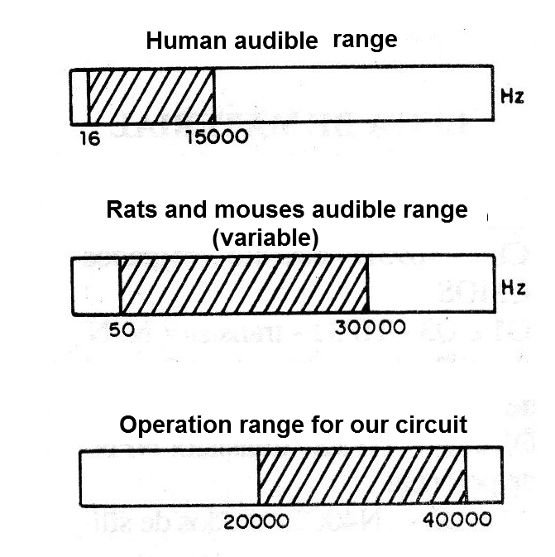
Taking into account that a continuous high-frequency whistle, above 20 kHz can be heard by these small animals, but it is beyond our capacity of hearing, it is evident that a generator that produces it bothers the animals and is not even perceived by us humans.
Nowadays, there are high-power generators with good power that are suitable for use in silos, pantries and other places that can be attacked by rats and other rodents.
The apparatus we describe is experimental, generating sounds in the range of 20 to 40 kHz and which are reproduced with good intensity by a tweeter.
If the reader has already exhausted the means of chasing away mice from a place and wants to experiment, this is a suggestion of a project that does not harm the environment, since it does not use chemicals of any kind (figure 1).

On the other hand, the circuit can be permanently connected with a small energy consumption which is certainly much less than the damage prevented by the attack of rodents or even the use of chemicals.
Characteristics
Supply voltage: 110/220 V
Power: 1 to 2 W (approx.)
Consumption: 1.5 to 5 watt
Frequency of operation; 20 to 40 kHz
HOW IT WORKS
To generate the high frequency signals we use a well known configuration of our readers that is the oscillator, using one gate of the 4 available in an integrated 4093.
This oscillator has its frequency determined by C1 and by setting P1.
This adjustment must be done experimentally, whether with the use of a frequency meter or with the use of a captured animal, to determine its sensitivity as a function of the tuned range.
The other three gates of the integrated circuit are used as inverter buffers to drive the final power step.
The two gates (Cl-1b and Cl-1c) form the first buffer that excites the pair of complementary transistors Q1 and Q2.
By reversing the signal from these two gates we have Cl-d which excites the second pair of complementary transistors Q3 and Q4.
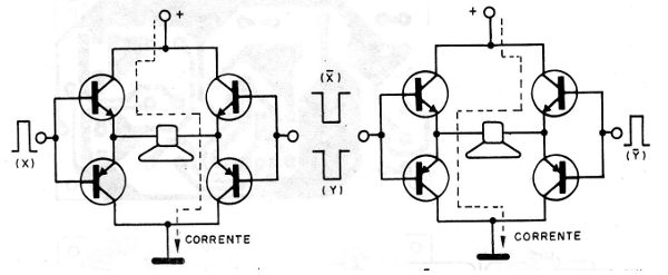
In this way, the transistors of each pair alternately conduct the current that passes in a half-cycle and in another always through the tweeter as shown in figure 2.

The power supply basically consists of a transformer with a secondary 9 V that after rectification and filtering become approximately 13 V continuous for powering the circuit.
Remember that the built-in should not be fed with more than 15 V.
The transistors, with this voltage, develop a good audio power, even needing to be equipped with small heat radiators.
The tweeter must be able to reproduce a good signal giving preference to piezoelectric types that reach the higher frequencies, such as those generated by this circuit.
These tweeters are equipped with a small output transformer which guarantees them the low impedance required to operate on this circuit.
However, other types of tweeters can also be experienced.
The LED is to indicate that the unit is switched on since we will not be able to hear any sound emitted.
ASSEMBLY
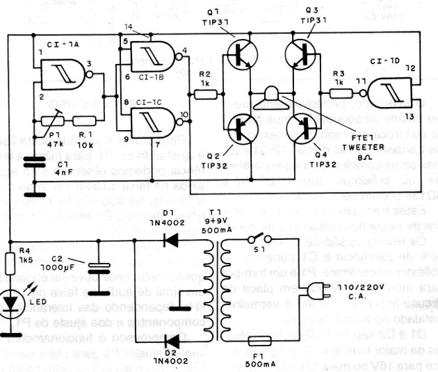
In figure 3 we have the complete diagram of the device, including its power supply.

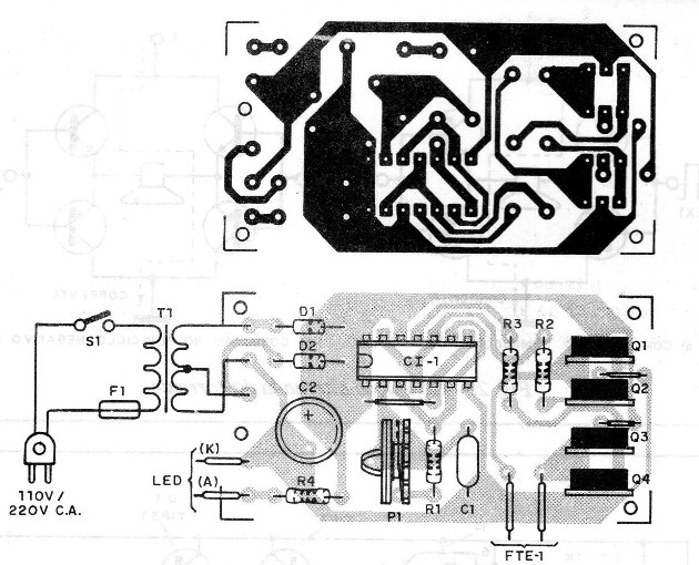
In figure 4 we have our suggestion of printed circuit board for the assembly.

The integrated, preferably must be equipped with a DIL socket that would facilitate its exchange in case of necessity.
The transistors are of type TIP31 and 32, but complementary or close complementary pairs like BD137 and BD138 can be used.
These transistors must be equipped with small heat radiators.
The resistors are 1/8 W with 5 to 20% tolerance and C1 can be polyester or ceramic. P1 is a trimpot for vertical mounting on printed circuit board and the LED is red, installed in the box panel.
D1 and D2 are 1N4002 or higher voltage equivalents and C2 is an electrolyte for 16 V or more. The transformer must have 9 + 9 V secondary with a current of at least 500 mA.
The primary must be according to the local network.
TEST AND USE
To test the unit simply turn it on and adjusting P1 for maximum resistance we can get an acute sound still in the audible range around 12 to 14 kHz. If this is not achieved, momentarily switch C1 with a 10 nF capacitor.
Another way is to connect to pin 4 or 10 of the integrated one frequency meter where an audio signal in the range of 12 to 50 kHz is to be found depending on the tolerances of the components and the setting of P1.
Once the operation is confirmed, we must adjust P1 to obtain an ultrasound.
With the frequency meter, simply adjust to a frequency between 18 and 22 kHz which is the range where the tweeter is most efficient.
By ear, simply place the trimpot in a position just above where we no longer hear the sounds emitted.
It is only necessary to install the appliance in the desired location and to leave it permanently connected.
CI-1 - 4093B - CMOS integrated circuit
Q1 and Q3 - TIP31 - NPN power transistor
Q2 and Q4 - TIP32 - NPN power transistor
D1 and D2 - 1N4002 - silicon diodes
LED - common red LED
T1 - Transformer with primary according to the local and secondary network of 9 + 9 V x 500 mA
S1 – On-Off switch
F1 - 500 mA - fuse
FTE-1 - piezoelectric or mobile coil tweeter
C1 - 4n7 - ceramic or polyester capacitor
C2 - 1000 uF x 16 V - electrolytic capacitor
R1 -10 k x 1/8 W - resistor (brown, black, orange)
R2 and R3 - 1k x 1/8 W - resistors (brown, black, red)
P1 - 47k - trimpot
R4 - 1k5 x 1/8 W - resistor (brown, green, red)
Miscellaneous: printed circuit board, power cable, DIL socket for the integrated, Heat radiators for transistors, fuse holder, mounting box, wires, solder, etc.


