Features:
Supply voltage: 9 and 12 V DC
Current: less than 1 mA
HOW IT WORKS
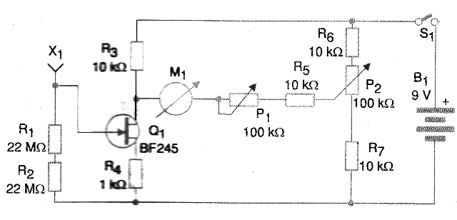
The electrical charges captured by a sensor cause very little current at the base of transistor Q1, affecting its polarization. Consequently, the emitter current of Q1 is applied to the base of a Darlington BC517 super-transistor, with a gain of 30,000 times, affecting its conduction state.
The amplified signal then appears at the emitter load resistance which is P2. P1 adjusts the resting current of the instrument so that it corresponds to the center of the scale of the instrument employed.
Thus, depending on the polarity of charge of the captured ions, we have an increase or decrease of current in this instrument. This deflection allows us to evaluate not only the quantity but also the polarity.
Even without using field effect transistors (FETs) that would be the ideal elements for this type of application, the circuit has excellent sensitivity.
ASSEMBLY
The indicating instrument is a low cost moving coil microammeter with approximately 200 uA full scale. The complete diagram of the device is shown in Figure 1.

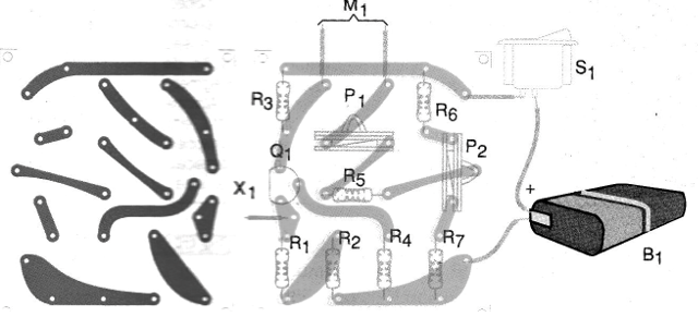
The arrangement of the components on a printed circuit board is shown in Figure 2.

For the X1 sensor we have several possibilities, such as a small telescopic antenna, a stranded wire loop or even a small metal sphere 2 to 5 cm in diameter.
The stranded wire can be used because the plastic cap "captures" the ions which induce in the conductive element the voltage that will act on the circuit.
In fact, we should never touch any charged or metal objects on the sensor, as direct discharge into the gate of the field effect transistor may cause it to burn out. The power can be done with a 9 V battery, since the consumption is very low thus ensuring a good durability for it.
TEST AND USE
Turn on the power and set P2 so that the current indicated by the instrument is half scale. Then bring a loaded comb or charged ball pen (without touching) to the sensor.
To charge the objects rub them on a wool blouse or other fabric. Adjust P1 so that the needle does not exceed the full scale. Then, moving a ballpoint pen apart and approaching it on a piece of wool or silk fabric should move the needle of the instrument.
The instrument must acknowledge the charges accumulated in this body, which are positive. To use the device, simply approach (without touching) the sensor to the body where you want to detect charges.
To detect the charges in the environment, simply observe the needle indication and move the device a few times. Charges from a cloud in a thunderstorm can be detected by connecting the circuit to an external antenna. However, during the storm keep the circuit disconnected from the antenna as it can be dangerous.
Q1 - BF245 - JFET Field Effect Transistor
Resistors: (1/8 W, 5%)
R1, R2 - 22M ohm - Red, Red, Blue
R3, R5, R6, R7 - 10 kohm - brown, black, orange
R4-1K ohm - brown, black, red
P1, P2 - 100k ohm - trimpot
Miscellaneous:
X1 - Sensor - see text
M1 - 0-200 uA- microammeter
S1 - Single Switch
B1 - 9 V - battery
Printed circuit board, assembly box, knobs for potentiometers, battery connector, wires, welding, etc.


