Minerals in rocks, sand and dirt, some insects, and common materials as cardboard and plastic fluoresce with beautiful colors when illuminated by an ultraviolet source.
Interesting projects for high school science can be performed using this circuit.
This ultraviolet lantern operates with a 6 V battery formed by four D cells (alkaline or NiCad), and current drain ranges from 100 to 400 mA, depending on R1 and the characteristics of the transformer and the UV tube.
The ultraviolet source is a UV tube rated from 4 to 7 W such as the GE F6T4/BLB (6 W). All the components can be housed in a plastic box.
The lamp is mounted in a PVC tube with a handle and a long cable to connect it to the circuit.
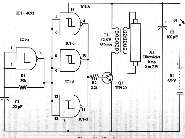
The circuit driving the lamp is a simple inverter formed by a low-frequency oscillator (IC1-a) and an output stage formed by Q1. IC1-b, c, and d act as buffers. Values of resistor R1 and capacitor Cl can be varied to achieve better performance.
A schematic diagram of the Ultraviolet Lamp is given in Fig. 1.

All the components are placed on an universal printed circuit board except the power supply, S1, the transformer, and the ultraviolet tube.
The printed circuit board is fixed inside a enclosure with common screws and spacers. Transistor Q1 must be mounted on a heatsink.
To use this device, close S1 to power up the circuit. You’ll hear a light hum from the transformer, indicating oscillation. Some visible light will be produced by the lamp, which indicates circuit operation.
IC1 - 4093 CMOS integrated circuit
Q1 - TIP120 NPN Darlington power transistor
T1 - 12.6 V, 350 mA transformer
X1 - Ultraviolet lamp, GE F6T4/BLB or equivalent, 4 to 7 W
S1 - SPST toggle or slide switch
B1 - 6 V, four D cells, alkaline or NiCad
R1 - 39,000 Ω, 1/4 W, 5% resistor
R2 - 2,200 Ω, 1/4 W, 5% resistor
C1 - 0.22 µF ceramic or metal film capacitor
C2 -100 µF, 16 WVDC electrolytic capacitor


