Obs. The original version of this article was published in a Brazilian magazine and translated into English to be part of my book Bionics for the Evil Genius (TAB – 2006).
The bionic trap described here uses a fluorescent lamp and an additional resource for capturing or killing the insects. In the basic version, the insects are collected in a bag, but we will also describe a high-Voltage killer in this site.
It is up to the reader to alter the circuit to capture the insect or animals according to the kind of light or radiation suitable for the species.
In the basic version, the circuit consists of a high-Voltage inverter used to drive a small fluorescent lamp from cells or batteries. The fluorescent lamp is chosen according to the type of insects the rader intends to capture. Visible light lamps or ultraviolet (UV) lamps with a power of up to 4 watts can be used in this circuit, such as the ones shown in Figure 1.
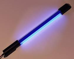
The use of an inverter is important if the reader In tends to capture insects in the forest or other places where an AC power line outlet would not be accessible.
The reader can use this device to collect specimens during the night in many different places.
Of course, using cells, the life of the supply is not very long, only 1 or 2 hours, so it is recommended that rechargeable cells be used for this purpose. For a larger autonomy, requiring many hours of supply for the circuit, larger batteries should be used.
Experiments
Many types of insects can be used in bionic experiments or other interesting applications, but the reader must first capture them. This project explains how to build a trap. This trap serves many uses, especially if the reader lives in an area where insects are a problem.
The main applications for the bionic trap are as follows:
Capture insects for experiments or applications in bionics.
Capture insects that are disturbing to people.
Collect insects for studies in biology.
Kill insects that are harmful to plants.
Power a fluorescent lamp, such as an emergency lamp.
Connect the high-voltage output to an electrifence.
How it Works
To convert a low DC voltage, such as the ones supplied by cells and batteries, into a high AC voltage, the recommended configuration uses a transformer.
But to drive a transformer it is necessary to change the pure DC current into a pulsed or alternating current because transformers can’t operate with pure DC currents. Consequently, an electronic circuit is necessary to allow the transformer to interface with the DC power supp1y, as shown in Figure 2.
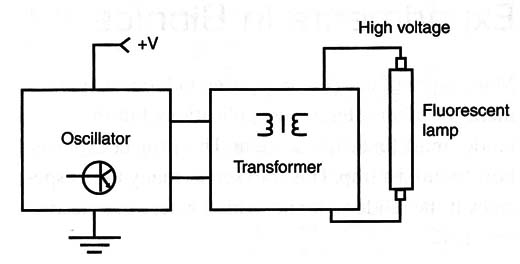
The circuit consists of a Hartley oscillator that produces an alternating signal that is applied to the low voltage coil of a small transformer.
In the secondary of this transformer, a high voltage appears, with peaks reaching more than 200 volts, enough to drive any fluorescent lamp, even the ones weak enough to no longer function anymore when connected to the AC power line.
C2 and C3 determine the frequency of the oscillator. Depending on the transformer, the reader must change the values of these components to find the ones that result in the best performance.
The reader is also free to change the resistor R1 to find the best performance matching with the characteristics of the transformer.
In the basic Version, four cells form the power supply. For the best autonomy, it is recommended that C or D cells or nickel cadmium (NiCd) rechargeable cells be used.
The circuit will drain between 100 and 300 milliamps, accordíng to the characteristics of the transformer used in the project and the lamp. For larger autonomy, use a 6-Volt battery.
Any small fluorescent lamp up to 4 watts can be used. The reader can use white lamps or UV lamps, according to the application. But íf the reader connects powerful lamps, even a 40-watt lamp. It will glow but with reduced brightness because the circuit can,t source more than a few watts to the load.
How to Build
Figure 3 shows the complete diagram of the bionic trap inverter.
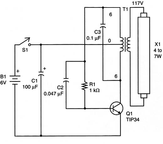
The circuit is very simple, so it can be mounted using a terminal strip as a chassis, as shown in Figure 4.
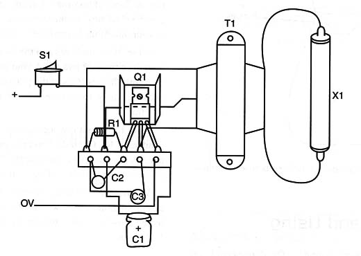
The transistor also needs a small heatsink. Take care not to invert the connections for this component when mounting the circuit.
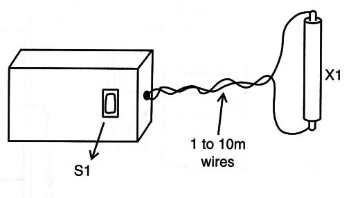
All the components should fit into a small plastic box, and to connect the lamp you can use a long wire, as shown in Figure 5.
Any type of transformer having a secondary with a center tap (CT) and voltages that range from 4.5 to 7.5 can be used. Currents range from 200 to 500 milliamps.
The primary wound can be rated to 110/117/120/127 /220 volts or 240 volts. The higher the voltage, the easier the lamp will be driven.
When connecting the lamp, take care with the isolation of the wires. The high voltage present in this part of the circuit is enough to cause a shock.
C2 and C3 are ceramic or polyester capacitors. The transistor is a TIP31 (with any suffix: A, B, or C) and equivalents such as the BD135 or even the TIP41 can be used. Using a TIP41 or 3 2N3055, the circuit can be powered from a 12-volt supply and larger lamps can be driven.
The trap can be made using several methods. One of them is shown in Figure 6 and consists of a bag placed under a lamp.
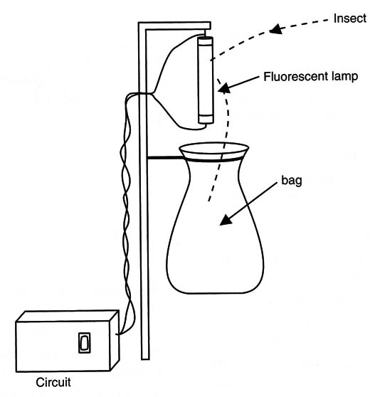
The insects attracted by the lamp beat against it and eventually fall into the bag where they are collected.
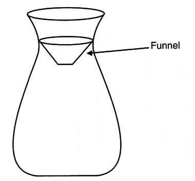
A resource for preventing the insects' escape from the bag can be added, as shown in Figure.7.
Testing and Using
Power the circuit on, closing S1. The fluorescent lamp will glow imediately.
If you lean down and place your ear near the transformer, you should be able to hear the sound of the oscillator.If no sound is heard and the lamp doesn7t glow, turn off the círcuit and take a good look at your mounting. Something is wrong.
If the transistor heats and the lamp doesn”t glow, turn the circuit off and check your mounting. Take care with the positions of the polarized components, because if they are inverted, the circuit won’t function.
Once the circuit is working, the reader can try changes in R1, C1, and C2 to get a better performance.
A practical idea is to place a 10 kilo-ohm trimpot in a series with R1, adjusting the output power. When the circuit runs as expected, the reader can install it in an area where insects will be collected. Now is the time to experiment with white or UV lamps.


