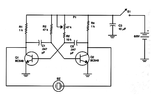
Figure 1 shows a circuit that uses two transistors to produce a tone in the range determined by C1 and C2, and adjusted by P1. It consists of an astable multi vibrator driving a piezoelectric transducer or a small loudspeaker.

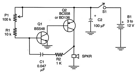
Another circuit using two complementary transistors is shown in Figure 2. This circuit can drive a loudspeaker from 5 to 10 cm (4 or 8 ohm) when powered from 3 to 12 volts.

For voltages up to 6 volts Q2 must be replaced by a BD136 (or a TIP32) mounted on a small heatsink.
In this case, the output power will be up for some watts, ideal for experiments or applications involving large ranges.
The frequency depends on C1 and can be adjusted by P2. Replacing C1 by capacitors in the range of 0.4 to 2.2 µF, the circuit will produce very low-frequency pulses, such as a metronome.
Experiment to see the effect of this kind of audio stimulation on insects an animals.
Q1 : BC5481 or equivalent
Q2: BC558 or BD136 general purpose PNP transistor
R1: 10 k ohm 1/8 W resistor, brown, black, orange
R2: 1 k ohm x 1/8 W resistor, brown, black, red
P1: 100 kg lin or log potentiometer
C1: 0.047 µF ceramic or polyester capacitor
C2: 100 µF x 6 V electrolytic capacitor
SPKR: 5 to 10 cm 4 or 8 ohm small loudSpeaker
B1: 3 to 12 V batteries or cells
Other: PCB or terminal strip, plastic box, wires, solder, etc.
Using the 555 IC
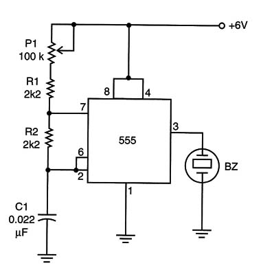
Figure 3 shows a tone generator using the 555 IC.

This version can drive a piezoelectric transducer and, adding a transistor, a small loudspeaker.
The basic frequency is adjusted by the potentiometer P1 and depends on C1. With the components shown in the circuit, the frequency can be adjusted from 100 Hz to 1 kHz, representing the normal range of sounds that repel or affect most small insects.
The reader is free to change the values of C1, generating sounds of any frequency, including supersounds.
Of course, when generating supersounds, an adequate transducer must be used, because small piezoelectric transducers have the reproduction range limited to 10 kHz.
A suitable transducer can be found in piezoelectric tweeters. In this case, the small transformer found inside the loudspeaker must be removed and the transducer directly coupled to the circuit.
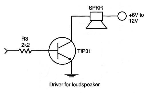
Another idea would be to use a transistor stage to allow the circuit to operate with low impedance loads. This circuit is shown in Figure 4.

This circuit can be used with common loudspeakers if operating in the audible range or it can use piezoelectric tweeters if operating in the supersound range.
IC-l: 555 integrated circuit - timer
P1: 100 ohm lin or log potentiometer
R1: R2: 2k2 X 1/8 W resistor, red, red, red
C1: 0.022 µF polyester or ceramic capacitor
S1: On/off switch fl Bl: 6 or 9 V cells or battery
X1: Piezoelectric transducer
For the transistor output stage:
Q1: TIP31 silicon NPN power transistor
R3: 2.2 k ohm x 1/8 W resistor, red, red, red
SPKR: 4 or 8 Ω loudspeaker or tweeter
Other parts: PCB or solderless board, battery connector or cell holder, plastic box, wires, solder, heatsink for the transistor (if used), etc.


