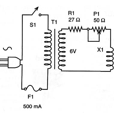
A very simple way to generate an alternating magnetic field with the frequency of the power line is shown by the circuit in Figure 1.

The advantage of this circuit is the reduced number of components. Otherwise, the main disadvantage is that it has a fixed frequency: 60 Hz.
The strength of the field can be adjusted selecting the resistor in series with the coil. The resistor has an important role in limiting the current to secure values.
A current larger than that supported by the transformer can burn this component.
The coil is the same used in the basic experiment (BM021E).
This circuit has the advantage of not being plugged directly to the AC power line. The transformer adds isolation, meaning that anyone can touch live parts of the circuit without the danger of shock hazards.
T1: 117 VAC (or 220/240 VAC) primary and 6 V x 300 mA to 500 mA secondary transformer
R1: 27 Ω x 5 W wire-wound resistor
P1: 50 Ω wire-wound potentiometer
X1: Coil (see text)
S1: SPST on/off switch
F1: 500 mA fuse and holder
Other: Power cord, terminal strip or PCB, box, solder, wires, etc.


