Note: This article was originally written in Portuguese for the author's website in 2004, and later (2006) used in the book Bionics for The Evil Genius. Some changes to the original text were introduced.
What we are proposing here is an interesting project that allows blind people to sense their environment by using a device that converts light into sound. Like an elementary eye (a very simple, one-pixel version of an eye), the project creates complex sounds because it uses four sensors, the same way insects have eyes that arc multifaceted. Here we will be using light sensors, each one acting as a single image point or pixel sensor.
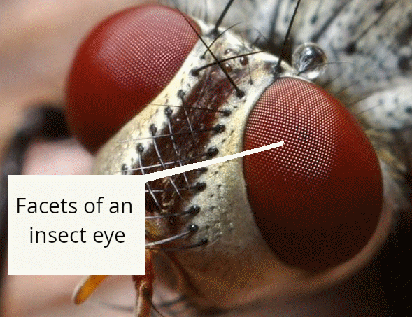
The number of points of image seen by an insect depends on the number of facets in its eye, as shown in Figure 1. The number of facets in common insects varies between 50 and 5,000, but its eyesight would be considered to suffer from poor definition compared to humans or even a common charge-coupled device (CCD) photographic camera that has some millions of pixels of definition.
The idea of bionic vision, replacing natural vision. is to reproduce the image sensor (the eye), connecting it to the optical nerve or sending the information to the brain some other way. In this way, a damaged eye can be replaced by an electronic image sensor connected directly to the optical nerve.
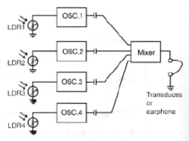
Our project works with an interesting idea that can be explored starting from its simplicity. The project consists of a four-pixel sensor that converts the amount of light picked up by each facet into a sound, as shown by Figure 2.
Of course, the evil genius is free to increase the number of facets and even create a high-definition project using CCD image sensors or optical resources, such as image-scanning systems.
The tones produced by each facet are combined to produce an output signal in a small loudspeaker or earphone. The eye of the device is placed in the per-son's hand so that it can explore the environment, generating a sound image. With some experience, it will be possible to know what each change in a tone represents. The person will be able to recognize sim-ple objects such as an open door or window or the presence of moving things.
Bionic Applications
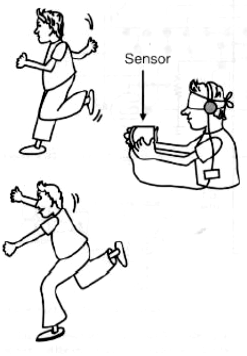
The project is experimental and will appeal to the curious. The evil genius can use it to create a game where a blindfolded friend must find his or her way to a group of people using only the signals given by the bionic eye, as suggested by Figure 3.
Other applications include the following:
• Experiments with artificial vision II
• Create a simple vision system interfaced with the computer
▪ Design an alarm that can recognize forms
How the Circuit Works
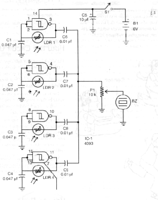
The sensors consist of light-dependent resistors (LDR) that control the frequency of the oscillators. A 4093 integrated circuit (IC) formed by four NAND gates is used for the four independent oscillators, which are controlled by the four LDRs.
The basic frequency of each oscillator is deter-mined by the corresponding capacitor. The signals in the output of each oscillator are mixed and applied to a high-impedance transducer.
Since the oscillator drains low currents and the transducer doesn't need much power to be activated, power consumption for the circuit is very low. The four AA cells that power the circuit can be used during many weeks or even months without the need for replacement.
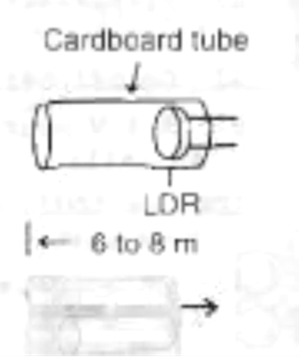
The sensors (LDRs) are mounted together, forming a multifaceted eye. A lens and small cardboard tubes are used to add directivity and sensitivity to the eye.
How to Build
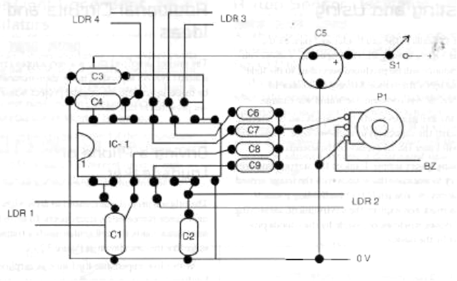
Figure 4 shows the schematic diagram of the bionic eye.
The basic circuit can be mounted on a printed circuit board (PCB) or a solderless board. Figure 5 shows a suggestion for a PCB for this mounting.
The LDRs are common, round types with diameters that range from 1 to 2.5 centimeters. Smaller types are better because they can be easily mounted inside thin cardboard tubes. When mounting, take care with the positions of the polarized components, such as the IC and power supply.
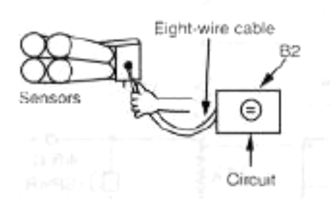
The electronic part of the circuit fits inside a plastic box, and the sensor is connected to the circuit by a short cable, as shown in Figure 6.
The sensor consists of four cardboard tubes mounted as shown in Figure 7.
To add sensitivity and directivity, a small plastic lens can be placed in front of each sensor. The LDR must be placed in the correct position near the focus of each lens. The transducer is a small loudspeaker or, if the reader prefers, an earphone.
Testing and Using
Place the cells in the cell holder and turn on the power supply, closing Si. Then open the volume control. Sounds will be produced according to the light picked up by the sensor. Moving the sensor to explore the environment, the sound will change.
lf the evil genius wants, the sounds can be altered, replacing the capacitors in each oscillator. Higher values will lower the frequency of the sounds. Using is very simple: Explore the surrounding area and try to associate the sounds with the image sensed by the circuit. You could try blindfolding yourself with a mask and explore the environment, identifying open doors, windows, or people by the sounds produced by the device.
Parts List
Required Parts
IC-1: 4093 CMOS integrated circuit
B2: Piezoelectric transducer
S1: On/off switch
B1: A 6 V source of four AA cells
LDR1 to LDR2: Any LDR (see text)
P1: 10 Id/ potentiometer, lin or log
C1 to C4: 0.047 µF ceramic or polyester capacitor
C5: 10 µF x 12 V electrolytic capacitor
C6 to C9: 0.01 µF ceramic or polyester capacitor
Other: PCB or solderless board, plastic box, material for the transducer, cell holder, wires, solder, etc.
Additional Circuits and Ideas
The project described here is a very simple version of a bionic eye. As suggested, many improvements can be made, upgrading the original project. Some ideas are provided in this section.
Driving a Phone or Loudspeaker
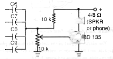
The original project was created to drive high-impedance piezoelectric transducers. To drive low-impedance loads, the evil genius needs a transistor stage like the one shown in Figure 8. With a low-impedance load such as earphones or a loudspeaker, power consumption increases, reducing the battery life.
Other Light-Dependent Oscillators
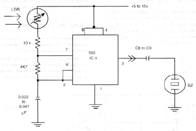
Figure 9 shows another light-dependent oscillator using the 555 IC that is suitable for a bionic eye.
The main disadvantage when using this circuit is that you will need one chip for each oscillator, increasing the size and cost of the project.
Consumption can be reduced if the complementary metal oxide semiconductor (CMOS) version of the 555 (7555) is used. The current drain of each oscillator in this case will fall to less than 1 milliamp.
A Two-Sensor Oscillator
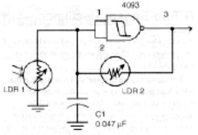
Another idea for a bionic eye project is to implement two sensors controlling one oscillator, as shown in Figure 10.
The interesting characteristic of this circuit is that when light increases on sensor 2, the frequency of the oscillator also increases. Otherwise, when light increases on sensor I, the frequency falls to a point where the oscillations are cut. This means that the circuit can be adjusted to sense a determined light intensity range.
Seeing in the Dark
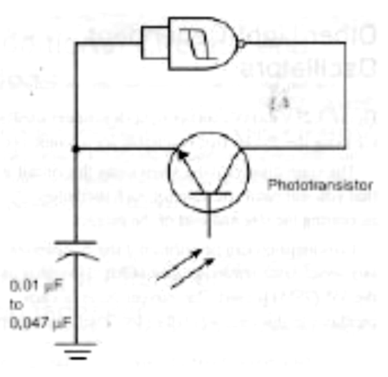
Phototransistors and many LDRs can see infrared (IR), or invisible, light. This means that, with the use of appropriate filters at the front of the sensor, it is possible to use the device in the dark. Figure 11 shows how to control the oscillators using phototransistors instead of LDRs.
Using the Computer
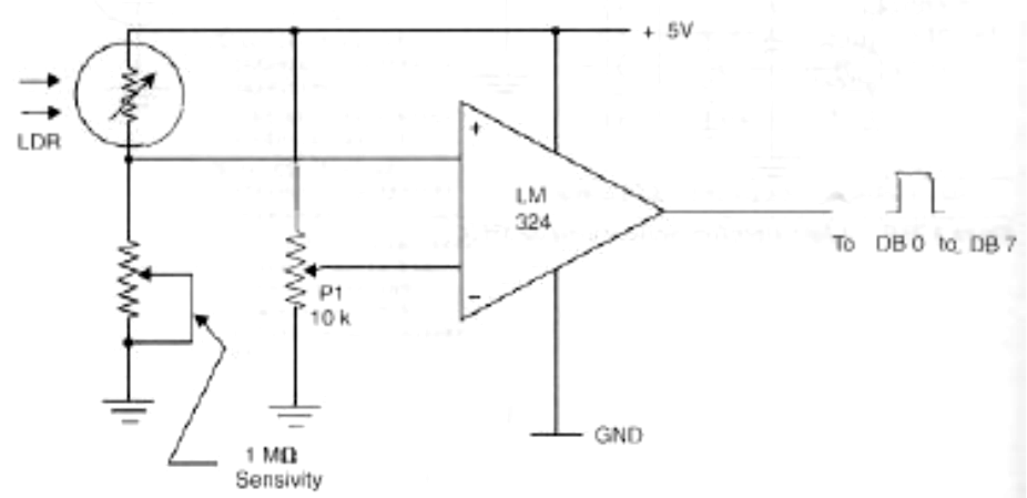
Powering the circuit with a 5-volt supply, the information picked up by the sensor can be translated into a digital form, as shown in Figure 12.
Using the input/output (I/O) port (parallel port) configured to receive data, the evil genius can develop a program to create an image, starting with the information scanned from the bionic eye.

