The project described here imitates nature, creating a circuit that can receive weak sounds and repro-duce them via headphones. The sensitivity of the project can be upgraded to pick up sounds that even creatures in nature cannot detect. Our project consists of a very sensitive amplifier coupled to a microphone with special resources to pick up weak sounds from distant places or even through walls. For example, one device can pick up a conversation that is far away or on the other side of a wall, in the same way a spy microphone picks up sounds.
Bionic Replications
The basic idea involved in this project is to create an ear, linking an electronic amplifier circuit to resources, such as sound lenses and sensors, in order to pick up very weak sounds. The electronic circuit is created by our technology, and the acoustic capabilities for picking up the sounds are based on solutions found in nature.
Such solutions would consist of the shape and characteristics of the ears of many animals that depend on their hearing for their survival. As Figure 1 shows, the ears of a rabbit operate as acoustic shells, picking up sounds coming from a determined direction and concentrating them into the sensor, or the car drum.
A bionic ear can be used for many interesting applications such as the following:
Creatures like the rabbit depend on good hearing to survive.

• You can use it to bear conversations through walls or in distant places.
• The sensitivity of the ear can help you find leakage in water plumbing.
• Noise sources can he easily located.
• You can explore the nature of hearing or recording sounds produced by many living beings.
How the Circuit Works
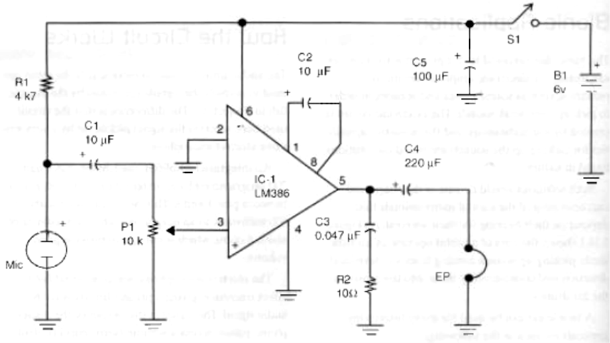
The audio amplifier has no secrets: It is the same one used to amplify the signals generated by the electric fish in Project 3.1. The difference is that the circuit used here receives the signal picked up by a very sensitive electret microphone.
An integrated amplifier, the LM386, has a gain of 200 programmed by an external capacitor plugged in between pins 1 and 8. This circuit can source about 500 mill watts to an earphone with an impedance of about 8 ohms, which is enough to provide good volume.
The electret microphone has an internal field effect transistor, giving a pre-amplification to the audio signal. The signal in the output of the microphone passes across a volume (sensitivity) control formed by a potentiometer and is then amplified to the input of the amplifier.
The circuit is powered from four AA cells. Because the current drain is not high, the cells' life will he extended to many hours of continuous use.
The electret microphone will be installed in acoustic resources according to the application. Figure 2 shows some of the resources recommended for this project.
The acoustic shell or the acoustic apparatus for hearing through walls is very important for concentrating all the possible sound into the microphone. These aspects will be described later in this section.
How to Build
Figure 3.14.3 shows the complete diagram of the electronic circuit for the bionic ear.
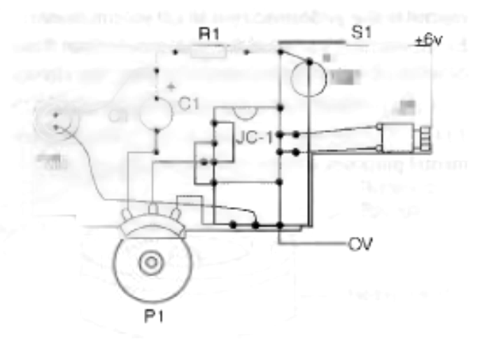
The printed circuit board (PCB) is the same as that recommended for the electric fish project, because R1 and the microphone can he mounted externally, as shown by Figure 4.
Of course, the other difference in the project is that, instead of a loudspeaker, the output load is an earphone. The same figure shows how to connect this transducer.
The circuit fits into a small plastic box, and to be easily used a handle is added, as shown in Figure.5.
The microphone is connected to the circuit by a long, shielded cable to avoid noise, mainly the hum produced by the AC power supply lines.
When mounting, take care with the position of the polarized components such as the integrated circuit (IC), electret microphone, power supply, and electrolytic capacitors. Any inversion will prevent the circuit from operating.

Acoustic Resources
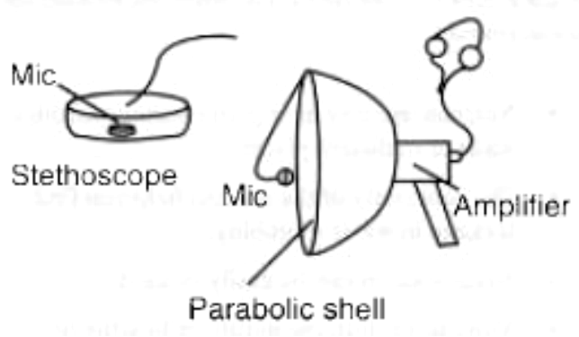
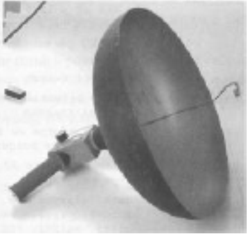
The simplest acoustic aid is a small plastic shell with the microphone placed at its center, as shown in Figure 6. Using this, it is possible to pick up sounds from one particular direction.
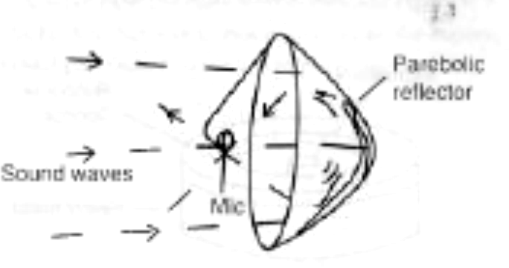
An exactly parabolic shell is the ideal for picking up weak remote sounds, such as the ones found in nature. The reader can hear the song of birds or pick up a conversation from a long distance, as suggested by Figure 7.
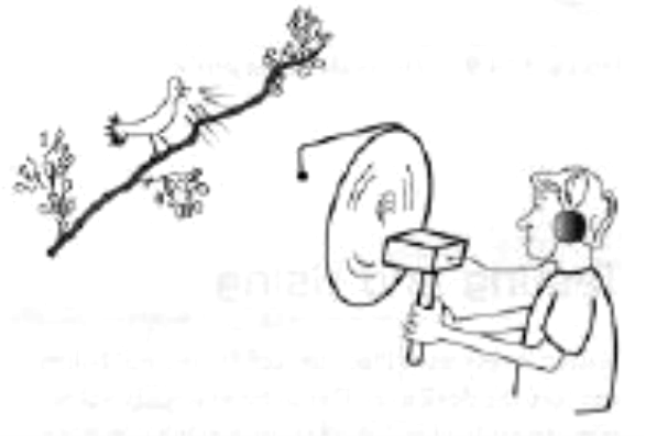
The larger the parabolic shell is, the more sound can be concentrated into the microphone. For practical purposes, shells with diameters between 40 and 80 centimeters are recommended.
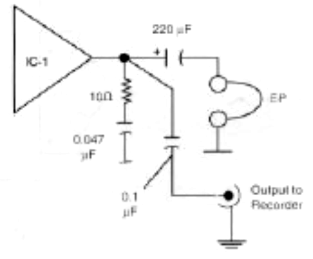
If the evil genius wants, he or she can add an out-put line to a small tape recorder to the circuit, as shown in Figure. 8.
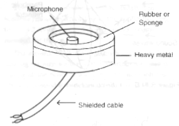
Another acoustic resource would be a stethoscope made with a heavy piece of metal and a plastic sponge, as shown in Figure 9. Using this unit, the evil genius can hear sounds through walls.
Testing and Using
Testing is very easy. Place the cells in the cell holder and turn the device on. The ambient sounds will be reproduced loud and clear in the headphones when you open the sensitivity control. When using the device, all you have to do is point the microphone or stethoscope at the sound source.
Parts List
Required Parts
IC1: LM386 (any suffix) integrated circuit audio amplifier
R1: 4.7 kΩ x 1/8 W resistor, yellow, violet, red
R2: 10 Ω x 1/8 W resistor, brown, black, black
C1, C2: 10 µF x 12 V electrolytic capacitor
C3: 0.047 µF ceramic or polyester capacitor
C4: 220 µF x 12 V electrolytic capacitor
C5: 100 µF x 12 V electrolytic capacitor
P1: 10 kΩ potentiometer log
S1: On/off switch
MIC: Two terminals electret microphone
B1: A 6 V source or four AA cells and holder
EP: Earphone 8 to 32 Ω
Other: PCB, earphone jack, plastic box, acoustic apparatus, wires, solder, etc.
Additional Circuits and Ideas
In principle, any small audio amplifier powered from cells, or a battery can be used to amplify the signals of an electret microphone. The evil genius can also use other types of transducers to pick up signals from nature, and two suggestions are provided here.
Using the TDA7052
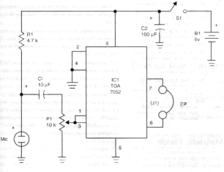
An audio amplifier suitable for applications where electret microphones are used is the TDA7052. The basic circuit for this application is shown in Figure 10.
The circuit is powered from four AA cells and can produce about 170 mill watts) to 8-ohms earphones in the basic configuration: The input for the electret microphone is the same, and the sensitivity or volume control is also performed by a 10 kΩ potentiometer. Earphones with an impedance that ranges from 8 to 64 ohms can be plugged into the output of the circuit.
A small PCB for this circuit is shown in Figure 11. Another way to mount this circuit, for experimental purposes, is to use a solderless hoard.
Parts List
Required Parts:
IC-1: TDA7052 integrated circuit audio amplifier
R1: 4.7 kΩ x 1/8 W resistor, yellow, violet, red
P1: 10 kΩ potentiometer log
C1: 10 µF x 12 V electrolytic capacitor
C2: 100 µF x 12 V electrolytic capacitor
S1: On/off switch
B1: A 6 V source or four AA cells and holder
J1: - Output jack for the earphones
MIC: Two terminal electret microphone
Other:
PCB, plastic box, cell holder, wires, knob for the potentiometer, solder, etc.
Hearing Magnetic Fields
Although some living beings, such as pigeons, can sense magnetic fields, no discovery has ever been made of a creature that produces magnetic fields for some special use.
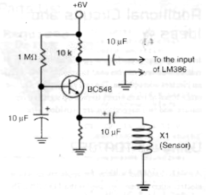
If the evil genius wants some adventure trying to discover some "magnetic creature," a magnetic sensor can replace the microphone in our basic project. The assembly process for this is shown in Figure 12.
This circuit is also useful for detecting sources of magnetic noise such as power lines and electric appliances.
During usage, all that is required is to place the sensor in the suspected area and try to hear the sound of magnetic fields, which will be heard as a hum in the earphones.
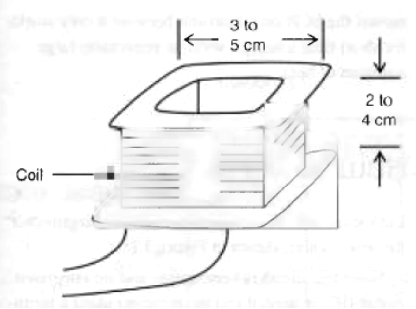
The circuit is housed in a small, plastic box. X1, the sensor, consists of 500 to 10,000 turns of enameled wire 28 to 32 AWG in a plastic or cardboard form, as shown in Figure 13.
The primary winding of any transformer can be used as a sensor; simply remove the metal core. A ferrite rod inside the coil will increase its sensitivity. Just place the sensor near the AC power lines, transformers, or electric appliances, and hear the noise produced by their magnetic fields.

