Note: This article was originally written in Portuguese for the author's website in 2004, and later (2006) used in the book Bionics for The Evil Genius. Some changes to the original text were introduced.
Nature has equipped all creatures with sensitive temperature monitors that tell them when they reach an uncomfortable state. The sensors can also trigger defense mechanisms such as the ones that cause your hair to stand up or that cause perspiration.
What we will describe in this chapter is a simple project that monitors the environment's temperature, like the sensors in our skin, and that triggers an alarm if it rises to an uncomfortable value or falls below another fixed value. The circuit can be installed any place where sensitive creatures live, such as greenhouses, aquariums, or areas where insects and microorganisms are common. In other words, the device monitors the ecosystem, triggering an alarm if the temperature is not appropriate for its existence.
By changing the sensor, the circuit can also be used to monitor the amount of light in an environment, triggering an alarm if the place becomes too dark or too bright. The alarm is a beeper driving a piezoelectric transducer or a loudspeaker.
The Bionics
The device imitates the sensors found in many living creatures and can be used in the following applications:
• Control the temperature of a greenhouse or other monitored area.
• Sound an alarm in case of fire.
• Alert someone if heaters or refrigeration systems fail due to energy cuts or other causes.
How the Circuit Works
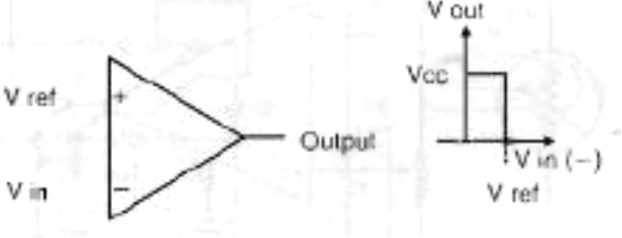
Voltage comparators are very high gain operation amplifiers, having two inputs, as shown in Figure 1.
Wiring a voltage divider at the inverting input ( - IN) determines a reference voltage (REF) at this point. If the input voltage is less than the reference voltage, the output remains low (0V). But if the input voltage is higher than the reference voltage, the out-put goes high (Vcc).
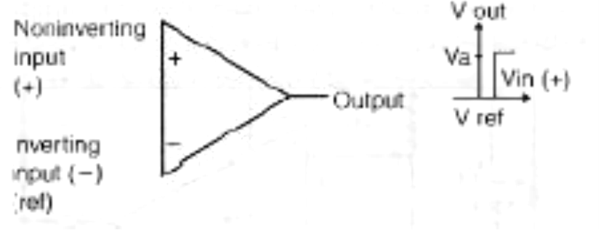
We can connect the device so that it operates in the opposite manner. If the reference voltage is applied to the noninverting input (4-IN), the output is high (Vcc) when the input is less than the reference voltage, and the output is low when the input voltage is higher than the reference. This performance is shown in Figure 2.
Two comparators operating in different modes can he combined so that they become what is known as a window comparator. This circuit is shown in Figure 3.
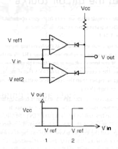
As we can see, two reference voltages are applied to the comparators, V1 and V2. If the input voltage is lower than VI or higher than V2, the output is low. The output is high only if the voltage is in the range comprised by V1 and V2.
If a temperature transducer provides the input, we can convert voltage into temperatures. The output of the circuit will be at the high level if the temperatures are between the values adjusted by the references. The output of the circuit passes to an inverter so that a two-tone oscillator is triggered when the temperatures are out of the adjusted range.
The evil genius can make some improvements to this circuit, such as adding a relay to power a heater or a cooler according to the application.
How to Mount
Figure 4 shows the complete circuit of the ecological monitor.
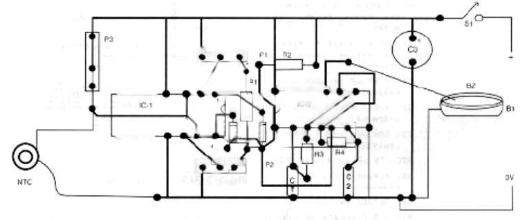
The circuit is mounted on a printed circuit board (PCB) or a solderless hoard. A PCB pattern is shown in Figure 5.
The sensor is a common negative coefficient resistor (NTC), a device that changes the resistance as a function of temperature. Essentially, it is a temperature sensor.
P3 must have values that are twice the NTC resistance or more at a normal temperature. For instance, if the NTC is a 10k type, use a 22 to 47 k potentiometer. Types with resistances at normal temperatures (ambient or 20' C) between 10 and 100 kilo-ohms can be used.
The operational amplifier can be replaced by an equivalent device. Even common types such as the 741 can be used. The only concern is choosing an operational amplifier that operates with low-voltage sources (6 volts).
Most of these devices have a linear characteristic (that is, the resistance changes in direct ratio to the temperature), making easier adjustments based on a common thermometer.
The sensor can be placed far from the circuit, and if exposed to water or environmental conditions, it is recommended that you protect it using glass, epoxy, or other substances. Of course, when protected, the device will take longer to respond to temperature changes.
When mounting, the position of polarized components such as integrated circuits (ICs) and the power supply must he observed. The circuit has a very low current consumption and this means that the calls will have an extended life. If the evil genius wants, a power supply can be used to provide energy to this project.
Testing and Using
Close S1 to power the circuit on. Adjust P1 and P2 to stop the alarm if it is activated. P3 adjusts the sensitivity of the circuit, so start from the point where P3 is in the maximum resistance.
First, place the sensor in a cold place (using some ice, for instance) and adjust P1 to trigger the alarm. Find a point where, breathing on the sensor, the alarm stops.
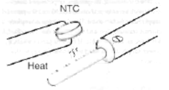
Now place the sensor near a soldering iron, as shown in Figure 6. Do not touch the sensor to the iron. Adjust P2 to trigger the alarm.
This is a simple, basic adjustment. A more accurate adjustment can be made, using a thermometer as a reference. Once adjusted, the sensor can be installed where the temperature must be monitored.
Parts List
Required Parts
IC-1: LM324 integrated circuit operational amplifier
IC-2: 4093 CMOS integrated circuit
D1, 02: 1N4148 general-purpose silicon diode
P1, P2: 10 kΩ trimmer potentiometer
P3: 10 kΩ to 1 MΩ trimmer potentiometer (see text)
R1: 10 kΩ x 1/8 W resistor, brown, black, orange
R2: 4.7 kΩ x 1/8 W resistor, yellow, let, red
R3: 1 MΩ x 1/8 W resistor, brown, black, green
R4: 47 kΩ x 1/8 W resistor, yellow, violet, orange
C1: 0.47 µF ceramic or polyester capacitor
C2: 0.047 µF ceramic or polyester capacitor
C3: 100 µF x 12 V electrolytic capacitor
NTC: 10 kΩ to 470 kΩ NTC
BZ: Piezoelectric transducer
S1: On/off switch
B1: A 6 V source or four AA cells
Other: PCB or solderless board, wires, cell holder, solder, etc.
Additional Circuits and Ideas
The basic circuit can be altered to perform other functions, and some suggestions are given in this section.
Driving a Relay
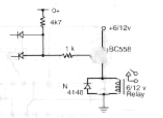
Figure 7 shows how to drive a relay when the temperature falls below an adjusted value or rises above the value.
Six- or 12-volt relays can be used. The only concern in this case is to use the power supply voltage according to the relay. Types with a 50-milliamps coil are the best.
Using a Diode as Sensor
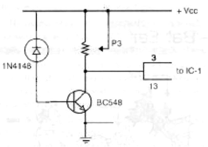
Common diodes can also be used as sensors, as shown in Figure 8.
When using diodes, a transistor must be added to increase the current in the circuit to a value that can drive the operational amplifier. Any silicon diode can be used as a sensor. Adjustments are made the same way as in the basic version.
Monitoring Light
Figure 9 shows how to replace the NTC with a light-dependent resistor (LDR) to monitor the light of a particular environment.
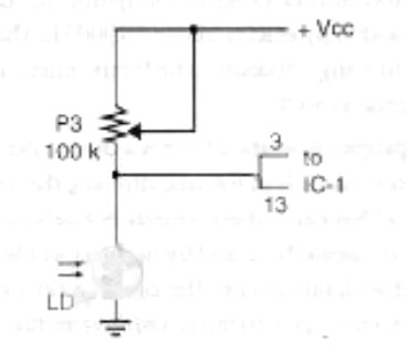
Any common LDR can be used. P3 adjusts the sensitivity of the circuit according to the light range to be monitored. Other resistive sensors such as pressure sensors or position sensors (potentiometers) can be used in this project.
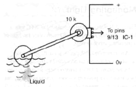
Figure 10 shows how to use a potentiometer as a position sensor, monitoring the level of water in a reservoir.
The evil genius can also find many other applications for this circuit in monitoring bioprocesses.
