One of the pillars of bionics is that living matter can conduct an electric current. This means that many experiments can be done in which living beings are stimulated with electric currents to monitor their reactions.
The project described here focuses on experiments with electrically stimulating living beings, in particular those with a nervous system, which means mammals (including humans), fish, insects, and many others. Of course, the circuit can also be used to stimulate other beings, such as plants, microorganisms, and so on. The use of the circuit in bionics is limited only by the reader’s imagination.
The nerves stimulator consists of a high-voltage generator powered from simple cells. The circuit itself is quite simple and has no critical parts or adjustments. It is very important that the reader avoid the danger of connecting the device directly to the AC power line.
This means that, although the circuit can produce peaks of voltage reaching more than 200 volts, in the case of shock, the reader will experience a hard shock, but not a fatal one.
Of course, it is recommended that the reader never use this device with others without the presence of an adult or a teacher who could limit the effects of electric shocks. The circuit mustn’t be used on persons with pacemakers or heart problems.
Experiments
Many experiments can be suggested using this project:
You can use the circuit to show how the human nervous system senses different voltages.
Experiments with living beings, such as fish in an aquarium, can be conducted to show how an alternating electric field can alter their behavior.
Plants and other beings can be stimulated in experiments at a lab to see how their circadian rhythms and general behavior are altered.
Experiments can be conducted to test if pain can be controlled by nerve stimulation (under the supervision of specialists, of course).
A trap for insects can be created using this circuit.
How it Works
It is not possible to directly convert a low DC voltage into a high DC or AC voltage without of the use of special circuits. These circuits are called inverters and can be found in common applications, as in fluorescent lamps driven by common cells, or in car batteries.
To convert a low direct current (DC) voltage into a high alternating current (AC) voltage, the recommended configuration is to use a transformer. But to drive a transformer, it is necessary to change the pure DC current into a pulsed current or AC. Transformers can’t operate with pure DC currents.
Consequently, an electronic circuit is necessary to connect the transformer with the DC power supply, as shown by Figure 1.
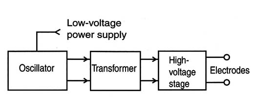
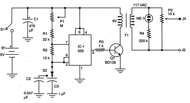
The oscillator produces current pulses, a square signal that, when applied to the base of the power transistor, is amplified and transferred to the low-voltage coil of a small transformer.
In the secondary coil of this transformer, a high voltage appears, with peaks reaching more than 200 volts, enough to stimulate any living being, including humans. To control the voltage applied to the specimen, a potentiometer is used. In parallel, a neon lamp indicates that a high voltage is being produced.
The frequency of the oscillator can be changed both by a potentiometer and selecting the timing capacitor (C2 or C3). This means that the bionics researcher can select the type of signal to be applied to the specimen under analysis.
When S2 connects the 0.047 µF capacitor, the circuit operates with a high-frequency signal between 100 Hz and 3 kHz approximately, adjusted by P1.
When S2 uses the 1 ,uF capacitor, the circuit produces low-frequency pulses, ranging from 0.1 to 3 Hz. The neon lamp will blink when the pulses are produced. The reader is free to change the capacitor if different ranges of frequencies are needed for the experiments.
The neon lamp is the best high-voltage indicator, because it only glows when the voltage across its terminals is more than 80 volts (typ, or typical). When glowing, the neon lamp only consumes a low amount of power, which does not affect the amount of high voltage produced by the circuit.
Four cells make up the power supply, and for the best autonomy it is recommended that C or D cells be used. The circuit will drain between 100 and 300 milliamps, according to the characteristics of the transformer used in the project.
Building
Figure 2 shows the schematic diagram of the nerves stimulator.
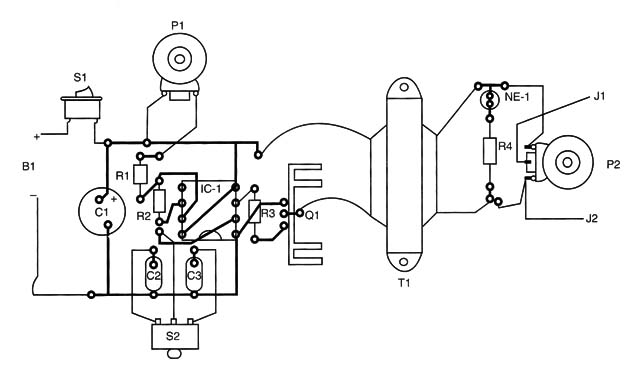
A printed circuit board (PCB) or a solderless board can be used to implement the project. A suggestion for a PCB pattern is shown in Figure 3.
The transformer is the only critical part of the project. Any small transformer having a primary rated for the AC power line and a secondary rated from 5 to 6 volts with currents ranging from 100 to 500 milliamps can be used. The final results, or the maximum output voltage, will depend on these components, so we recommend that the reader experiment with more than one transformer.
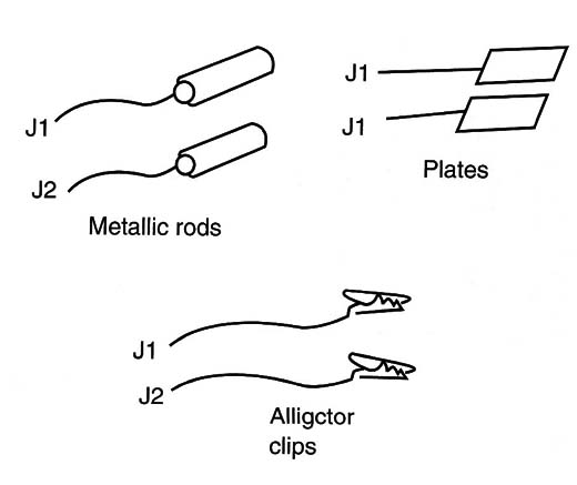
The probes depend on the experiment. Figure 4 shows some probes, which are used according to the experiment.
Testing and Usmg
Testing is very simple, especially if you are a courageous reader.
First, place the cells in the cell holder and turn on S1. Place S2 in position to connect C3, and after adjusting P1 you will see the neon lamp glow and flash.
If the neon lamp shows that a high voltage is being produced, you can pass to the next part of the test.
Put the potentiometer P2 in the minimum voltage output position and then hold the two wires connected to the output between your fingers, as shown in Figure 5.
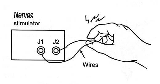
At first, the reader will feel a mild sensation, then discomfort, and then a painful shock. Of course, this is only a sample of what this circuit can do!
When using the circuit, start every time from the minimum of P2. Do not turn the circuit on before adjusting the output.
IC-1: 555 – Integrated circuit, timer
Q1: TIP31 (A, B, or C) NPN silicon power transistor
R1: 22 k ohm x 1/8 W resistor, red, red, orange
R2: 10 k ohm x 1/8 W resistor, brown, black, orange
R3: 1 k ohm x 1/8 W resistor, brown, black, red
R4: 220 k ohm x 1/8 W resistor, red, red, yellow
P1: 1 M ohm, lin or log potentiometer
P2: 10 k ohm lin Potentiometer
C1: 470 µF x 12 V electrolytic capacitor
C2: 0.047 µF ceramic or polyester capacitor
C3: 1 µF polyester or electroIytic capacitor
S1: On/off switch
S2: 1 pole x 2 positions SPDT
T1: Transformer (see text)
B1: A 6 V or four C or D cells and holder
NE-1: NE-2H neon lamp
J1, J2: Output jacks
Other: Plastic box, PCB or solderless board, knobs for P1 and P2, probes, etc.


